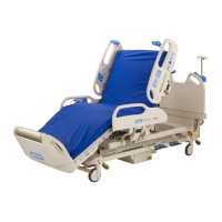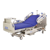
Do you have a question about the Hill-Rom CareAssist P1170 and is the answer not in the manual?
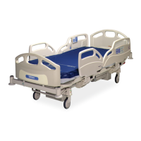
| Model | CareAssist P1170 |
|---|---|
| Type | Hospital Bed |
| Weight Capacity | 500 lbs (227 kg) |
| Trendelenburg Position | Yes |
| Reverse Trendelenburg Position | Yes |
| Battery Backup | Yes |
| Frame Material | Steel |
| Knee Gatch | Yes |
| Head Section | Adjustable |
| Foot Section | Adjustable |
| CPR Release | Yes |
| Overall Width | 39 in |
| Height Range | 15 in to 30 in |
| Side Rails | Yes |
| Power Source | Electric |
| Mattress Type | Foam or Air |
| Patient Controls | Yes |
| Wheels | Locking Casters |
| Warranty | Varies |
| Overall Length | 88 inches (223.5 cm) |
Provides detailed dimensions, environmental conditions, and electrical specifications for the bed models.
Details the different model numbers and their corresponding descriptions for the CareAssist® beds.
Offers essential safety precautions and warnings for servicing and operating the bed.
Provides initial guidance and context for beginning the troubleshooting process.
Lists common bed problems and directs users to the appropriate troubleshooting procedure (RAP).
Outlines a series of functional tests to verify bed operation and diagnose issues.
Troubleshooting steps for when none of the bed's functions are operational.
Specific troubleshooting steps for Scale Error 2, involving calibration and component checks.
Procedure to diagnose and resolve issues related to the CPR function of the bed.
Steps to troubleshoot and fix problems with the bed's braking system.
Explains the mechanical components and functions of the bed, like the frame and sleep surface.
Details the electrical specifications and operation for A Model beds.
Describes the characteristics and components of the bed's power supply unit.
Provides specifications and dimensions for the various motors used in the bed.
Details the electrical specifications and operation for B Model and newer beds.
References wiring diagrams for the electrical system of the bed.
Lists the necessary tools and supplies for performing maintenance and repairs.
Provides instructions for the removal and replacement of the sleep deck components.
Details the procedure for removing and replacing the AC power cord on A Model beds.
Instructions for removing and replacing the power supply unit on A Model beds.
Procedure for removing and replacing the battery backup on A Model beds.
Step-by-step guide for removing and replacing the head section motor.
Instructions for removal, replacement, and adjustment of the CPR cable.
Procedures for locating and replacing fuses in A Model beds.
Procedures for locating and replacing fuses in B Model and newer beds.
Instructions for removing and replacing the auxiliary outlet assembly.
Procedure for removing and replacing the SafeView™ Alerts components.
Information on how to identify and order replacement parts and contact technical support.
Details the policies for in-warranty and out-of-warranty parts exchanges.
Lists recommended spare parts for servicing multiple units.
Parts breakdown and illustration for the A Model beds base frame.
Parts breakdown and illustration for the A Model beds head siderail.
Parts breakdown and illustration for the A Model beds motor control box.
Parts breakdown and illustration for the B and C Model beds base frame.
Parts breakdown and illustration for the B Model beds head siderail.
Parts breakdown and illustration for the B Model beds motor control box.
Parts breakdown and illustration for the D Model and newer beds base frame.
Parts breakdown and illustration for the D Model and newer beds head siderail.
Parts breakdown and illustration for the D and E Model beds motor control box.
Guidelines for cleaning and disinfecting the bed and its components.
Information on the importance and schedule of regular maintenance for the bed.
A checklist detailing the maintenance tasks and their frequency.
Procedure for calibrating the bed's scale system.
Installation and removal instructions for the Infusion Support System (ISS) pole.
Instructions for installing and removing the oxygen tank holder.
Details on installing and removing the telescopic IV pole.
Instructions for installing and removing the mattress pad extender.
Procedure for installing and removing the traction frame support module.
