11
Ethernet-Schnittstelle
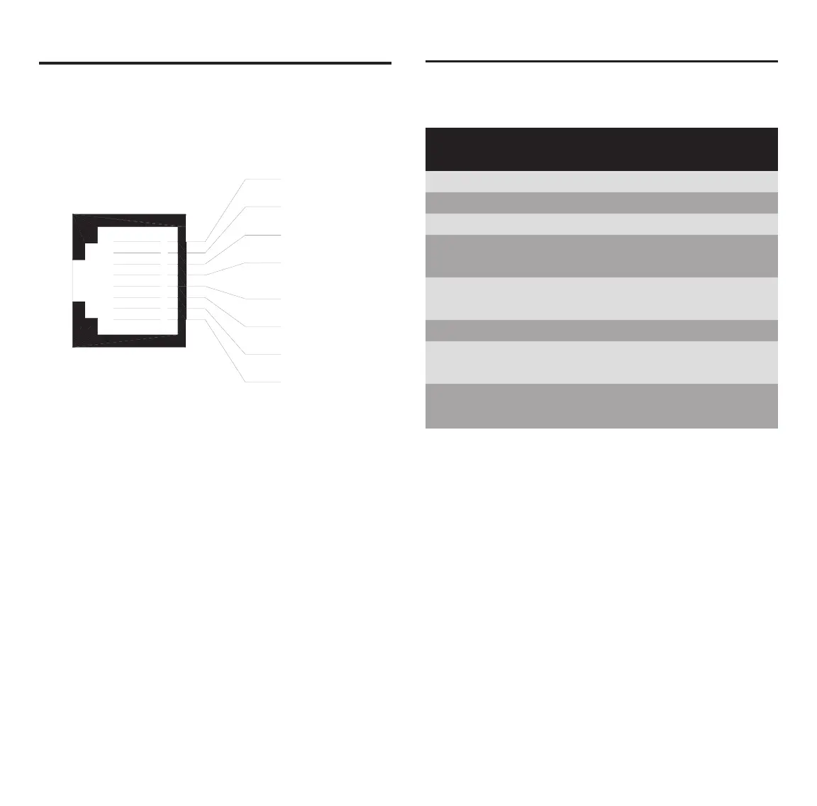
Ethernet-Pinbelegung an der RJ45-Buchse bzw. am
RJ45-Stecker.
Ethernet Interface
Ethernet pinning at the RJ45 female connector
respectively at the RJ45 male connector.
Pin Signal Bedeutung
Pin Signal Meaning
1 TX+ Sendedaten + / Transmitt Data +
2 TX– Sendedaten – / Transmitt Data –
3 RX+ Empfangsdaten + / Receive Data +
4 PE über RC-Schaltung mit PE verbunden /
connected with PC by RC circuit
5 PE über RC-Schaltung mit PE verbunden /
connected with PC by RC circuit
6 RX– Empfangsdaten – / Receive Data –
7 PE über RC-Schaltung mit PE verbunden /
connected with PC by RC circuit
8 PE über RC-Schaltung mit PE verbunden /
connected with PC by RC circuit
RJ45-Buchse / RJ45 female connector
For the Ethernet interface you use RJ45 plugs and
Twisted Pair cable of category 3 (CAT3) or 5 (CAT5)
which consists of 4 twisted cores and has a transmis-
sion rate of 10 MBit/s (CAT3 or CAT5) and respectively
100 MBit/s (CAT5).
It is recommended to use cable of category 5 (CAT5).
Für die Ethernet-Schnittstelle verwendet man RJ45-
Stecker und Twisted-Pair-Kabel der Kategorie 3 (CAT3)
oder 5 (CAT5), welches aus 4 paarweise verdrillten
Adern besteht und eine Übertragungsrate von 10 MBit/s
(CAT3 oder CAT5) bzw. 100 MBit/s (CAT5) hat.
Es wird die Verwendung von Kategorie-5-Kabeln
(CAT5) empfohlen.