NOTE:The red LED on the devices DXR1 and DXR2 diplays the reception of a radio signal, while the
green one diplays the transmission towards other devices. In the waiting phase, the red LED flashes to
diplay the proper functioning. Where it occur errors of connections the two LEDS flash alternately while
they flash together when the receivers are not enabled on the central computer.
1
1
2
2
Add. 32
Add. 33
Receiver 1
Receiver 2
DXR1
DXR1
ADDRESSE 32
ADDRESSE 33
1
1
2
2
-
-
+
+
A
A
B
B
ALTERNATIVE TO DXR2
JX1
JX2
JX1
JX2
JX1
JX2
-
JX1x1 JX1x2
JX1x3 JX1x4
JX1x5 JX1x6
JX1x7 JX1x8
JX1x9
JX1x10
JX1x11 JX1x12
JX1x13 JX1x14
JX1x15 JX1x16
JX1x17 JX1x18
JX1x19 JX1x20
JX1x21 JX1x22
JX1x23 JX1x24
JX1x25 JX1x26
JX1x27 JX1x28
JX1x29 JX1x30
JX2x1 JX2x2
JX2x3 JX2x4
JX2x5 JX2x6
JX2x7 JX2x8
JX2x9
JX2x10
JX2x11 JX2x12
JX2x13 JX2x14
JX2x15 JX2x16
JX2x17 JX2x18
JX2x19 JX2x20
JX2x21 JX2x22
JX2x23 JX2x24
JX2x25 JX2x26
JX2x27 JX2x28
JX2x29 JX2x30
SIR +12v
Manutenzione
Centrale
SIR
GND
S.A
V
R
KEY
A
B
-12V+
+INT GND 24H GND Z1 Z2 Z3 Z4
1
2
CX1
DXR2 Internal board
Receiver 1
Address 32 – fixed
NOTE: The transceiver DXR2
must be inserted with the
components face-down
Z8
Z5 Z6 Z7
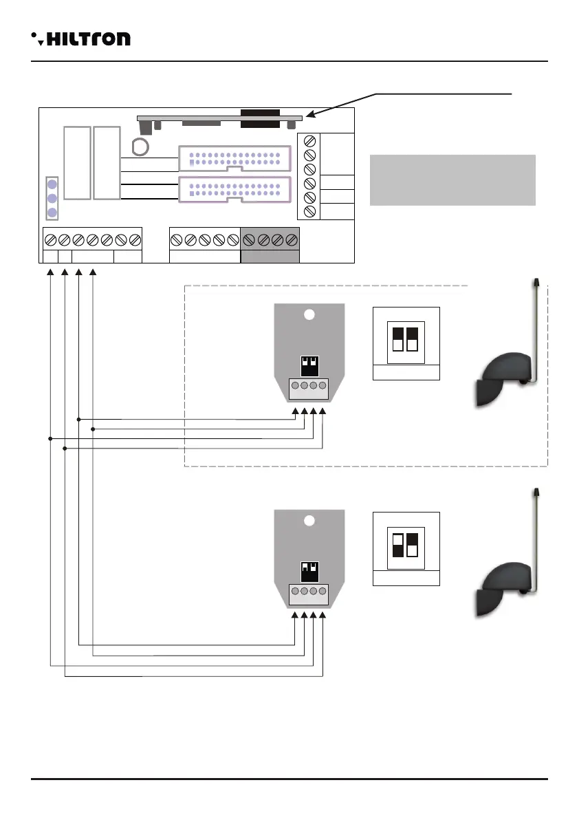
2.4.4 Connecting radio receivers DXR1/DXR2
Receiver1
Possibleconfigurations
Receiver2
Not present
Not present
Not present
DXR1 (Address 33)
DXR1 (Address 33)
A
B
D
E
F
Notpresent
Not present
DXR2 ( )Internal
DXR1 (Address 32)
DXR1 (Address 32)
DXR1 (Address 33)
C
DXR2 (Internal)
Installation
security
PROTEC4GSM - PROTEC8GSM - Installation guide and use
security
1110
In order to manage radio devices series XR (contact XR200, infrared sensors XR152 and XR8, siren
XR300, radio controls XR20 and DXR4) on this central computer it is possible to install two DXR1, or one
DXR1and one DXR2.
You can insert DXR2 into the connector CX1 of the board Easy-Connect inside the central computer that
assures the connection to the line RS485-DX bus.
NOTE: The transmitter DXR2 must be inserted with its components oriented towards the connectors of
the twin lead of connection to the central computer.
The DXR1 connects on the line DX bus as shown in figure, and can be positioned far from the central
computer so that its position can assure a better caverage for the radio signal of the ddevices of the series
XR.
On the central computer it is not possible to connect more than two transceivers.
As for the devices put on the DX bus, it is necessary to assign a univocal address to the transceiver.
The DXR2 connected to the inner part of the
central computer it is already set with the
address 32 and it can't be modified. It is
possible to assemble just one DXR2 on the
central computer, any transceiver in
addition to the first can be a DXR1 only
with address 33. The DXR1 has got a dip
switch with two positions with whom it is
possible to select a suitable address for the
central computer:
-32 with both the dip switch to set on off;
-33 with the dip switch 1 to set on on and 2
on off.
If you are using a DXR1 in addition to the
DXR2, it is necessary to programme it with the address 33.
The central computers PROTEC4GSM and PROTEC8GSM can accept transceivers with address 32 or
33 and it can't accept devices with a doubled address.
 Loading...