security
PROTEC4GSM - PROTEC8GSM - Installation guide and use
security
30
3.2.20 Devices (CONNECTORS)
Devices connected on the bus 485 must be enabled to allow for operating on the central unit.
Select the option :
And press or
With buttons to select device to enable o desable and press or
To modifiy the configuration .
For example by selecting :
(Upper on the right appear physical ID on the network RS485 )
Dial and the display shows:
If enable a device not connected on the central unit the display signale:
Devices that’s possible to activate on the bus 485 are:
- Console - with addresse 8.
- Connector 1 , 2, 3 e 4 - with addresses 16,17,18 e 19.
- Radio 1 and 2 (DXR2/DXR1) - with addresses 32 e 33.
- Module Link - with addresse 1.
Notes: every missed connection on an enabled device on the bus 485 is indicated on the display through
a message during the visualization of the status of the central unit, also when it doesn't generate an alarm
24h.
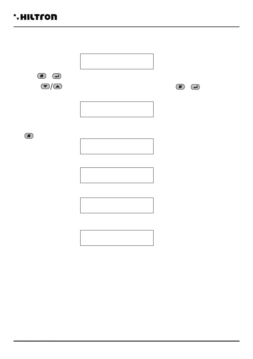
Devices 485
Connector 1 16
NOT Active
Connector 1 16
Link OK
Connector 1 16
Link BAD
Programming
31
3.2.21 Connectors Activation
Devices connected on bus 485 must be configured to allow the manage on the central unit.
To select the option :
And press or
With bottons to select the device to enable or disable and press or to modify the
configuration.
For example by selecting :
(Upper on the right appear physical ID on the network RS485 )
Dial and the display shows:
If enable a device not connected on the central unit the display signale:
When a device on bus 485 to manage generate an alarm 24h for failure connection (when enabled) on
display appear the indication:
Or if the device dispositivo in the meantime starts to engage with the central unit :
Devices that can be attivare sul bus485 are:
- Consolle - with addresse 8.
- Connector 1 , 2, 3 e 4 - with addresses 16,17,18 e 19.
- Radio 1 and 2 (DXR2/DXR1) - with addresses 32 e 33.
- Module Link - with addresse 1.
Notes: every missed connection on an enabled device on the bus 485 is indicated on the display through
a message during the visualization of the status of the central unit, also when it doesn't generate an alarm
24h.
To enable the connector 2 or next, to repeat the operation from the beginning of the page.
Connector 1 16
NOT ACTIVE
Connector 1 16
LINK OK
Connector 1 16
LINK BAD
Consolle 8
Link BAD
Connector 1 16
LINK BAD Mem.24H
Consolle 8
Link OK Mem 24H
 Loading...