2.3 Installation of the anti theft Tamper
· Drill a hole in correspondence with the placeholder on the base of the container and insert the plug
supplied.
· Tighten the screw leaving protrude from the mounting surface as required in order to keep the tamper
contact closed (6-10 mm).
· Place the plastic support in the hole on the base, fit the supplied spring on the pin button on the
tamper circuit, screw the tamper circuit on the two supports, inserting the protruding spring by the
button inside the plastic holder.
· Make sure that one the circuit is screwed the button must be pressed down, otherwise it will be
necessary unscrew the protruding screw from the mounting surface by a few turns so that protrudes
further.
· Engage the cable provided on the tamper card into the connector.
· The wires of the tamper must be connected in series to the protections of the devices on the line 24 h
of the connection card.
Screws +
dowels
PROTEC-ST
Two fixing screws
on the basis
PROTEC SERIES
Plastic
holder
5
2 Installation
2.1
!
!
!
!
!
!
General instructions
Do not install the central computer in extreme hot places or expose to bad weather.
In order to fix it safely and strongly it is appropriate to make sure to mount it on a flat surface.
Position the central computer at an easy access height in order to use the front panel.
Fix the bottom of the container on a flat and stable surface through the dowels, do 4 holes of 6 mm
corresponding to the angles of the container.
The connection cables of the external devices and the power cables can go in inside of the container
of the central computer through the hole that is in the middle of the bottom.
The connections must be carried out following the regulations CEI 79-3-2012 “Particular regulations
for the burglary systems, intruder, theft protection and anti-aggression.
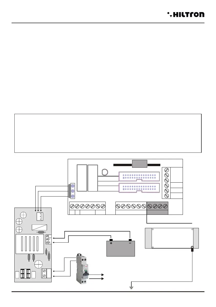
2.2 Power supply
The power supply system is provided by the power supply - charger that is inside the central computer that
keeps in charge the battery constantly (B12V7, 5Ah).
WARNING!
The mains voltage 230V must be connected to the power supply/charger through two double
insulation conductors of 1,5 mm² coming from a switch (Eg. Switch magnetermic) used for the
central burglar exclusively. Put in order the two conductors inside the central computer, block them
through the supplied cable gland, possibly by means of clamps.
In order to respect the safety legislation you need to carry out and verify the connection to the earth
system, as shown in figure.
Power Gap
Power supply
230V~
50Hz
Red
White
Black
Battery 12V
Red
Black
+Rif
12V
220V
GND
Insert the eyelet between the
metal panel and the central
circuit.
Central unit panel
JX1
JX2
JX1
JX2
JX1
JX2
-
JX1x1 JX1x2
JX1x3 JX1x4
JX1x5 JX1x6
JX1x7 JX1x8
JX1x9
JX1x10
JX1x11 JX1x12
JX1x13 JX1x14
JX1x15 JX1x16
JX1x17 JX1x18
JX1x19 JX1x20
JX1x21 JX1x22
JX1x23 JX1x24
JX1x25 JX1x26
JX1x27 JX1x28
JX1x29 JX1x30
JX2x1 JX2x2
JX2x3 JX2x4
JX2x5 JX2x6
JX2x7 JX2x8
JX2x9
JX2x10
JX2x11 JX2x12
JX2x13 JX2x14
JX2x15 JX2x16
JX2x17 JX2x18
JX2x19 JX2x20
JX2x21 JX2x22
JX2x23 JX2x24
JX2x25 JX2x26
JX2x27 JX2x28
JX2x29 JX2x30
SIR +12v
Manutenzione
Centrale
SIR
GND
S.A
V
R
KEY
A
B
-12V+
+INT GND 24H GND Z1 Z2 Z3 Z4
GND
Easy-Connect Board
CX1
Z8
Z5 Z6 Z7
Only PROTEC8GSM
4
Installation
security
PROTEC4GSM - PROTEC8GSM - Installation guide and use
security
 Loading...