(APPENDIX III) DIMENSIONS, WIRING AND MECHANICAL PARTS | PAGE 96
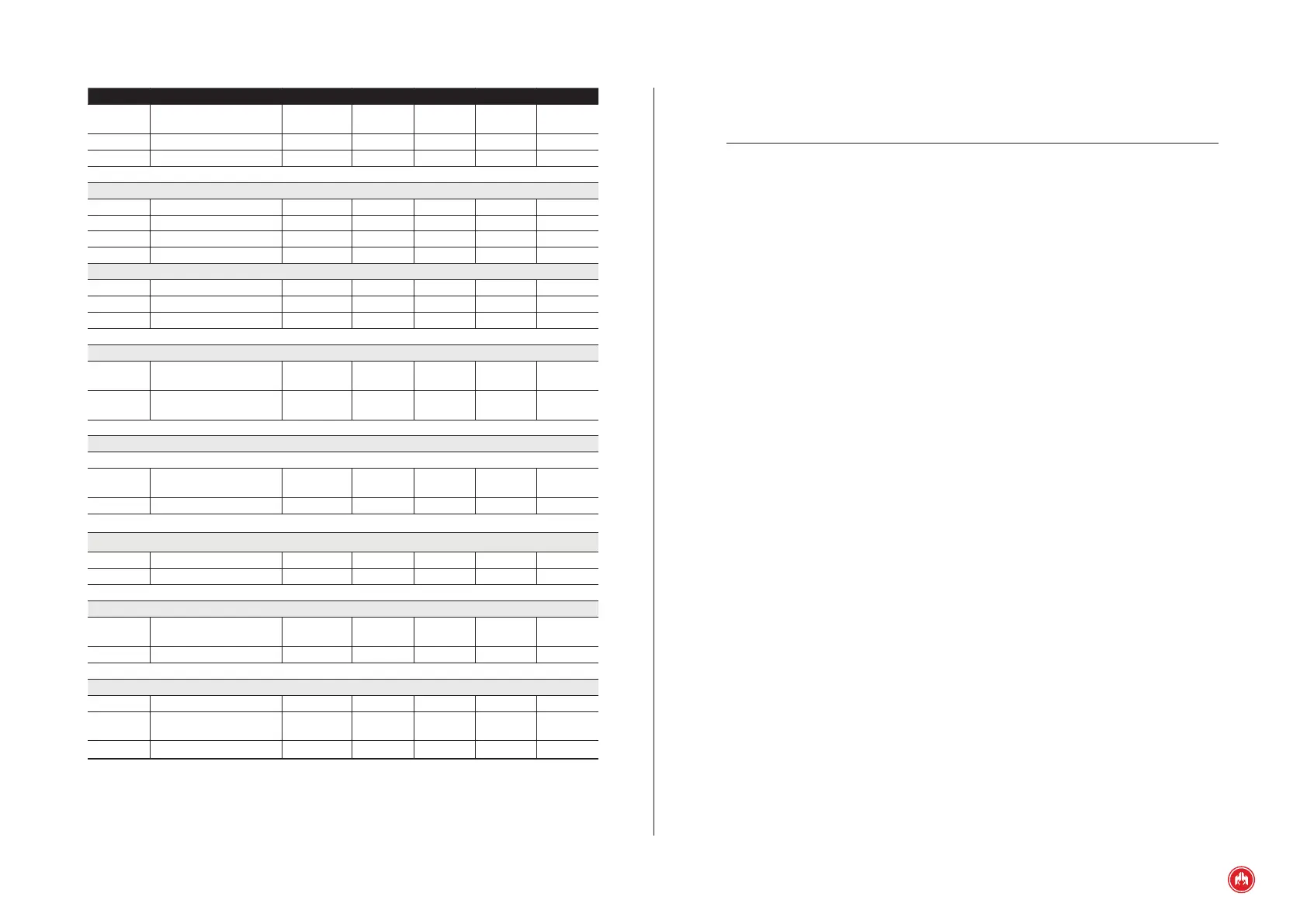
Symbol Parameter Conditions Minimum Typical Maximum Unit
R
T
Water temperature
resistance
0 4000 Ω
R
Anc
0 4000 Ω
DI 0 40 V
Power PNP outputs (terminals ARR, PR, PC)
V
O
Output voltage +BAT V
I
O
Output current T = ∞ 20 A
I
O
Output current T = 1s 40 A
PNP outputs (D+, AL, MA, SAL1, SAL2, SAL3 terminals)
V
O
Output voltage +BAT V
I
O
Output current 1 A
R
D+
Output resistance D+ 49.5 Ω
Analogue inputs for voltage measurement (VRN, VR1, VR2, VR3, VGN, VG1, VG2, VG3 terminals)
V
IN-FF
Input voltage phase to
phase
520 VAC
V
IN-FN
Input voltage phase to
neutral
300 VAC
Voltage-free relay outputs (CRC, CRNC, CRNA, CGC, CGNC, CGNA, SCC, SCNC, SCNA terminals)
Power relays
V
O
High voltage relay
contacts
250 VAC
I
O
Current relay contacts
cosφ = 1
8 A
Analog current measurement inputs (ILN, IL1, IL2, IL3 terminals)
I
IN
Input current 5 AAC
R
IN
Input resistance 0,02 Ω
Voltage-free relay outputs (BTC, BTNA terminals)
V
O
High voltage relay
contacts
250 VAC
I
O
Current relay contacts
cosφ = 1
5 A
Environmental conditions and protection of the enclosure
To Operating temperature -20 +60 ºC
H
R
Relative humidity
No conden-
sation
80 %
IP Degree of Protection *see note 1 65
NOTE 1:
IP 65 on the front of the control unit when installed on the control panel with
the sealing gasket provided.
The equipment has been designed and manufactured according to the require-
ments of the directives and harmonized standards which are applicable for com-
pliance with EC regulations.