PowerGem Plus User Manual
8
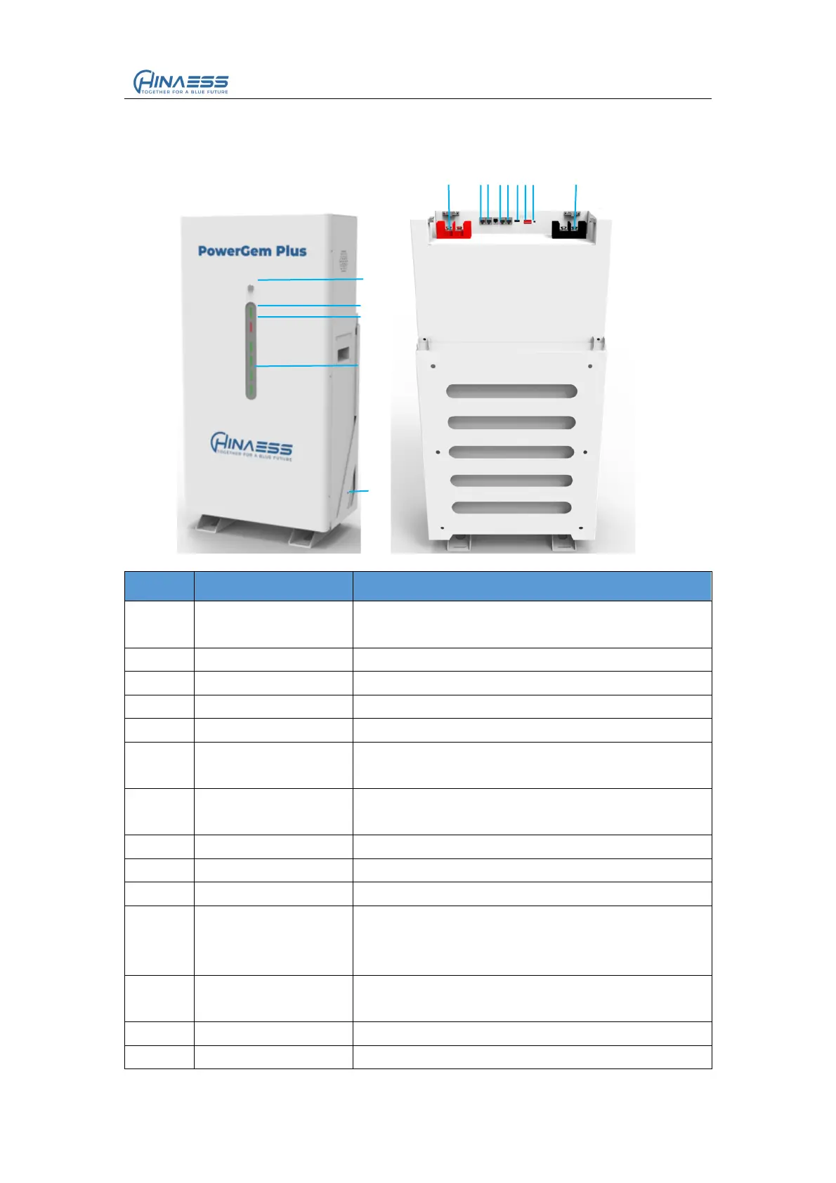
2.3 Interface Definition
This section elaborates the interface functions of the front interface of the device.
Figure2-1 The sketch of interface.
Table 2-3 Interface Definition
You need to press down it to wake up BMS.
And press back it to sleep BMS.
Follow the table” LED indicates instructions”
Follow the table” LED indicates instructions”
Follow the table” LED indicates instructions”
BAT+ for output and parallel
For communication between batteries,from last
module OUT to next module IN
For communication between batteries,from last
module OUT to next module IN
For the CAN protocol communication
For the RS485 protocol communication
Generally no need dial for both master and
slave,keep it 000000,only sometimes for special
protocols to set
Press it about 3s to wake up battery when it is in
force sleep state
BAT - for output and parallel