© Hirschmann Rev. G 10/05/15 190166_G.DOCXG
7 PRESSURE THEORY
The System measures the pressure of the boom lift cylinder for both rod- and piston-side. Both
sensors are contained within one box that also contains the electronics needed for amplification and
creation of the CAN-Bus signal.
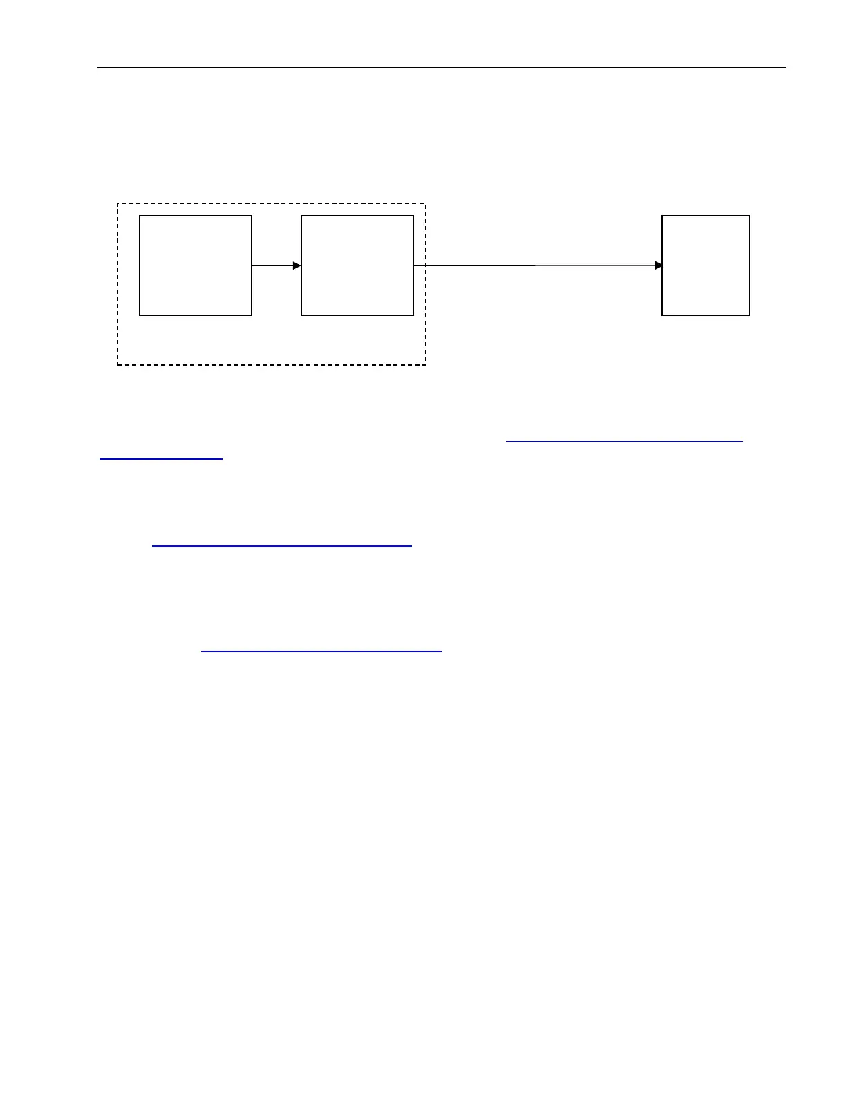
Block Diagram:
The signal runs from the pressure transducer as
digital information on the CAN-Bus to the central
unit.
So, what do you do when you are having a problem with your length read-out?
Start by checking the pressure display. Refer to the section “Troubleshooting A Sensor Problem
Using The Display” to call up the sensor signal on your console display.
The easiest spot to check the signal at is when there is no pressure applied to the sensor at all. The
only time this is for certain is when your pressure lines are drained and disconnected. In that case,
the readout should show about 500mV (+/- 25mV) and 0 PSI. Small variations could be adjusted; see
section Service Screen For Sensor Calibration.
The CAN-Bus is digital and as such will either transmit the signal correctly or not at all. If your
readings are off, chances are the pressure transducer is defective. Replace.
Note: After exchanging the pressure transducer block, BOTH transducer channels need to be zeroed,
see procedure Zero-Setting The Transducer Inputs.
DS 85
Console/
CU
Pressure Transducer
Pressure-
Cells
CAN-Bus
Converter
 Loading...