The Hirschmann HC3901 is a Load Moment Indicator (LMI) designed for various crane types, including telescopic boom cranes, lattice boom cranes, and all-terrain cranes. Its primary function is to provide the crane operator with essential real-time information to ensure operation within the crane's design parameters. This system operates on a reference/real comparison principle, continuously monitoring and comparing actual crane conditions with pre-programmed safe operating data.
Function Description:
The HC3901 LMI system provides critical data such as boom length, boom angle, working height, working radius, rated load, and the actual weight being lifted. It achieves this by utilizing various sensors, including an angle sensor and force transducers. When non-permitted conditions are approached, the LMI system issues warnings through audible alarms and warning lights. Furthermore, it can interface with the crane's control system to stop dangerous movements, such as lifting and luffing down, to prevent overloads and ensure safety.
The system is an operational aid, designed to warn operators of approaching overload and over-hoist conditions that could lead to equipment damage or personnel injury. It is crucial to understand that the LMI is not a substitute for good operator judgment, experience, or adherence to accepted safe machine operating procedures. The LMI primarily protects against overload in the boom's vertical range and does not account for non-vertical lifting, ground inclination, or derailed wheels.
Important Technical Specifications:
The HC3901 LMI system consists of three main components:
-
HC3901 Controller: This is the central processing unit and display.
- Processor: 16-bit high-performance processors.
- Communication Technology: CANopen.
- Operating Temperature: -20°C to +70°C.
- Operating Voltage: 11 to 36V DC.
- Operating Current: 200mA@24V.
- Communication Interface: 1×CANopen, 1×RS232, 1×SAEJ1939, 1×CANopen2.0B, 2×RS232.
- Installation: External and horizontal.
- Display Size: 5.7 inch.
- Program Memory: 2 x 2 MB.
- Data Memory: 2 x 1 MB.
- Input Analog: 6.
- Input Digital: 6.
- Output Digital: 6 (can be set to PWM output, reducing the number of digital outputs).
- Relay Output: 1 (max. 5A).
- Protection Class: IP65.
-
WG103 Angle Sensor: This sensor accurately measures the boom angle.
- Measuring Range: 0-90°.
- Output Signal: 4-20mA.
- Linearity Tolerance: <±0.2°.
- Hysteresis Tolerance: <±0.1°.
- Operating Temperature: -25°C to +70°C.
- Storing Temperature: -40°C to +70°C.
- Protection Class: IP65.
-
KMD Force Sensor: Designed for static and dynamic tensile force measurements, known for high overload capacity, fatigue strength, and corrosion resistance.
- Nominal Load Range: 1T up to 500T.
- Charge of Measuring Body: 200%.
- Charge of Measuring Body up to Flow Limit: 300%.
- Safe to Breaking Point: 500%.
- Linearity: <0.3% typ.
- Hysteresis: <0.5% typ.
- Protection Class: IP65.
- Operating Temperature Range: -40°C to +70°C.
Usage Features:
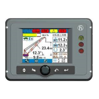
The HC3901 features a user-friendly operation and display interface.
- Data Display: Shows real-time operational data, including height status bar, jib angle, jib length, height, OM information, reeving, OM code, date and time, wind speed, rated load weight, actual load weight, boom angle, radius, and boom length.
- Indicator Lights: Provide visual cues for various statuses, including force-active warnings (yellow icons for LMI override, SET-UP mode, derricking in, rope limit override, A2B switch activated, slewing limit alarm, hoist protection alarms, A2B switch alarms, and main boom luffing angle limit alarm).
- Weight Status Bar: A color-coded bar indicating the load percentage:
- Green zone: 0-90% (safe range).
- Yellow zone: 90-100% (pre-warning range).
- Red zone: Exceeding 100% (overload warning range).
- Prewarning Light (Yellow): Illuminates when the load exceeds 90% of the nominal carrying load, indicating an impending overload.
- Overload Warning Light (Red): Illuminates when the load reaches 100% of the maximum carrying capacity, accompanied by an acoustic alarm. Load-moment-increasing crane movements are simultaneously switched off.
- A2B Switch Lamp (Red): Lights up when the heavy bob and spreader of the A2B switch meet, indicating maximum height has been reached. This triggers an alarm and stops hoisting and extending boom to luffing down movements. (Note: A2B switch signal does not input into LMI system, so this lamp is invalid for this specific model).
- Function Keys: Menu, buzzer, back, and confirmation keys, corresponding to symbols on the display.
- Rotary Button: Used for selecting function items and confirming selections.
- Operation Method: The system undergoes an automatic data initialization and self-checking process upon power-on. Operators must confirm the operating mode (OM) and reeving settings to match the actual crane configuration.
- Error Code Information: The system displays error codes and provides "Fault Help" to identify causes and suggested eliminations.
- Angle Limit Setting: Allows operators to set upper and lower angle limits for the boom.
Maintenance Features:
Regular inspection and maintenance are crucial for the LMI system's proper functioning and longevity.
- Inspection before Operation:
- Check all LMI components for damage.
- Verify normal display operation and absence of warnings or error indications.
- Confirm that the main boom angle, work radius, and load display match actual values.
- Routine Maintenance:
- Check the angle transducer for oil leakage.
- Inspect all cable insulating layers for damage and replace if necessary.
- Ensure the cable reel is sufficiently tight.
- Regularly clean the display for clarity.
- Routine Consideration:
- Protect the central unit (display), power supply cabin, and transducers from severe shaking.
- All parts of the LMI system are accurately adjusted and checked at the factory. Unauthorized dismantling of the housing is prohibited to prevent humidity and dust from affecting components.
- Buzzer Alarms: If the buzzer alarms without fault codes, check the cable connection to the A2B switch for disconnections or short circuits due to water ingress.
- Angle Sensor Adjustment: If the displayed angle or radius does not match the actual value (measured with an angle instrument between 0° and 70°), the angle transducer needs adjustment. This involves loosening three bolts, slowly turning the transducer until the displayed value matches the actual value, and then re-tightening the bolts.
- Troubleshooting: The manual provides an extensive "Error Code Table" detailing error codes, their causes, and elimination steps. This helps operators and service engineers diagnose and resolve issues. If problems persist, contact Hirschmann service.
- Time Setting: The time setting requires a password. Users are advised not to set the time themselves but to contact the manufacturer if the display shows the wrong time.
- CANbus Status Overview: The display shows the status of CANbus nodes (ID1, ID3) as green (working normally), yellow (preparing), or red (error/not-in-use).
- I/O Port Inquiry: Displays the status of digital I/O ports (DIN for digital input, DOUT for digital output) and allows inquiry of analog information.
- Load Inquiry: Enables operators to select the OM and view corresponding load charts based on boom length.