Home
Hirth
Engine
F 33 A/B
Page 30
Hirth F 33 A/B - Page 30
33 pages
Manual
Save Page as PDF
To Next Page
To Next Page
To Previous Page
To Previous Page
Loading...
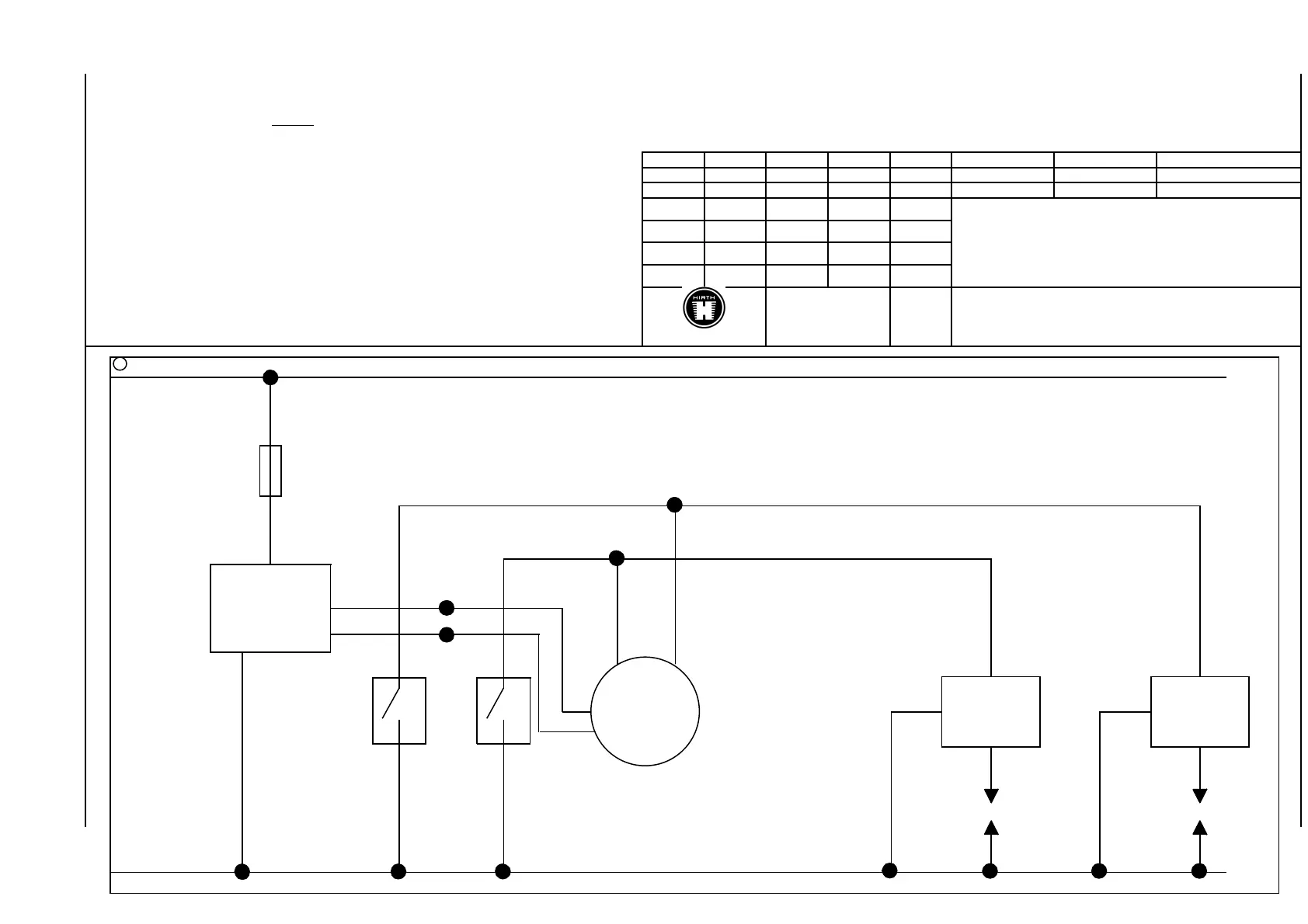
GH F33 BDA
Dieser Schaltplan versteht sich als Verlegungsvorschlag
f
Tag
Name
This wiring diagram is to be considered as a proposal for wi
ring
e
Gezeichnet:
07.01.99
Rögele
Leitungsquerschnitt allgemein: 1,5 mm
2
d
Geprüft:
07.01.99
Rögele
General size of line wire: 1,5 mm
2
c
Schalt
plan – EZ mit Generatorspule
b
Wiring diagram – SI with generator coil
a
Buchstabe
Anzahl
Änderung
Tag
Name
F 33
Rohteil-Nr.
Maßstab
Zeichnungs-Nr.
-
-
14 A 137
Stand: 02.02.05
DOC_F33_B_E_0.01
Sicherung
Fuse
5 A
Regler-
Gleichrichter
Rectifier-
Regulator
029.5
rot
red
Masse - Gehäuse
Ground - Case
braun
brown
Schalter
switch
gelb
yellow
gelb
yellow
schwarz
black
+
Zündung
Ignition
F 334 D1U
020.39/2
braun
brown
rot
red
Zündkerze
spark plug
023.26D
braun
brown
Zündspule
Ignition coil
020.39/3
Zündkerze
spark plug
023.26D
Zündspule
Ignition coil
020.39/3
rot
red
gelb-rot
yellow-red
gelb
yellow
29
31
Table of Contents
Main Page
Service Manual
1
Engine
1
Tel.: 0049-7144-8551-0, Fax: 0049-7144-5415
1
Manual
2
Chapter 0
3
Index
3
Chapter Designation Side
3
2 Operation of the engine 1-3
4
3Maintenance 1-7
4
4Wiring diagram ignition system 1-3
5
Chapter 1
6
Description of the engine, installation and technical data
6
Illustration 1.1.1-1 (Engine F 33 A)
6
Illustration 1.2.1-1 (Attachment threads)
9
Table 1.3-1
12
Illustration 1.4-1 (Identification plate position)
14
Table 1.5-1
14
Chapter 2
16
Operating of the Engine
16
Chapter 3
19
Maintenance
19
3.1 Generally
19
Initial Torque Values
19
Table 3.3-1
20
Chapter 4
26
Wiring diagram ignition system
26
Related product manuals
Hirth F-23
34 pages
Hirth 210R
21 pages
Hirth 2704
28 pages