EasyManua.ls Logo

Hisense 4AMW-105U4RAA User Manual

Hisense 4AMW-105U4RAA
66 pages
To Next Page IconTo Next Page
Page #1 background imageLoading...
Page #1 background image
TECHNICAL&SERVICE MANUAL V2.0
—MULTI-SPLIT TYPE AIR CONDITIONERS
R410A
Refrigerant
R410A
Refrigerant
R410A
Refrigerant
R32
Refrigerant
Models:
<Outdoor Unit>
AMW2-14U4RRA
AMW2-18U4RXA
AMW3-24U4RAA
AMW4-27U4RAA
AMW4-36U4RAA
2AMW-42U4RRA
2AMW-50URXA
3AMW-70U4RAA
4AMW-81U4RAA
4AMW-105U4RAA

Questions and Answers:

Hisense 4AMW-105U4RAA Specifications

General IconGeneral
BrandHisense
Model4AMW-105U4RAA
CategoryAir Conditioner
LanguageEnglish

Summary

1. GENERAL

1.1 Features

Key compressor and technology features for efficient air conditioning.

1.2 Product lineup

Details the types of outdoor units available in different configurations.

1.3 Model identification

Explains the coding system used to identify model specifications and features.

1.4 Working range

Specifies the operating voltage, imbalance, and temperature ranges for the unit.

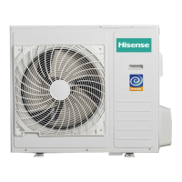
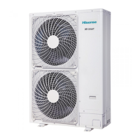
1.5 Product picture

Visual representation of outdoor units with their capacities.

2. SPECIFICATIONS

3. OUTLINES AND DIMENSIONS

4. ELECTRICAL DATA

5. CAPACITIES AND SELECTION DATA

5.1 Capacity characteristic charts

Charts showing outdoor unit capacity based on indoor and outdoor temperatures.

5.2 Piping length correction factor

Factors for adjusting capacity based on pipe length and height difference.

5.3 Correction factors according to defrosting operation

Modifies heating capacity based on defrosting operation impact.

6. SOUND PRESSURE DATA

7. REFRIGERANT CYCLE

8. WIRING DIAGRAM

8.1 Electrical wiring diagrams

Diagrams illustrating the electrical connections for different model series.

8.2 Electric control board

Detailed view and labeling of the electronic control board components.

8.3 Running Parameter Query

Instructions and parameters for checking outdoor unit running status.

8.4 Common Wiring

Illustrates standard wiring connections between indoor and outdoor units.

8.5 Sensor parameter

Provides resistance values for temperature sensors at various temperatures.

9. PIPING WORK AND REFRIGERANT CHARGE

9.1 MAX. Refrigerant pipe length and height difference

Requirements for pipe length and height difference for optimal performance.

9.2 Oil trap

Guidelines on when and how to install oil traps in refrigerant piping.

9.3 Additional refrigerant charge

Procedures for adding refrigerant based on piping length.

10. CONTROL MODE

Protection Functions

Covers anti-freeze, overload, and discharge temperature protection mechanisms.

Oil-return and Operation Modes

Explains oil return control, available operation modes, and mode conflict.

11. TROUBLE SHOOTING

11.1 Method to identify fault codes

Explains how to interpret fault codes displayed on the control board.

11.2 Fault codes

Lists fault codes for outdoor and indoor units with descriptions and solutions.

12. CHECKING COMPONENTS

12.1 Check refrigerant system

Details procedures for checking the refrigerant system using pressure gauges.

12.2 Check parts unit

Identifies components like fan motors and compressors and their checks.

Related product manuals