41
:
:
:
heat pump type
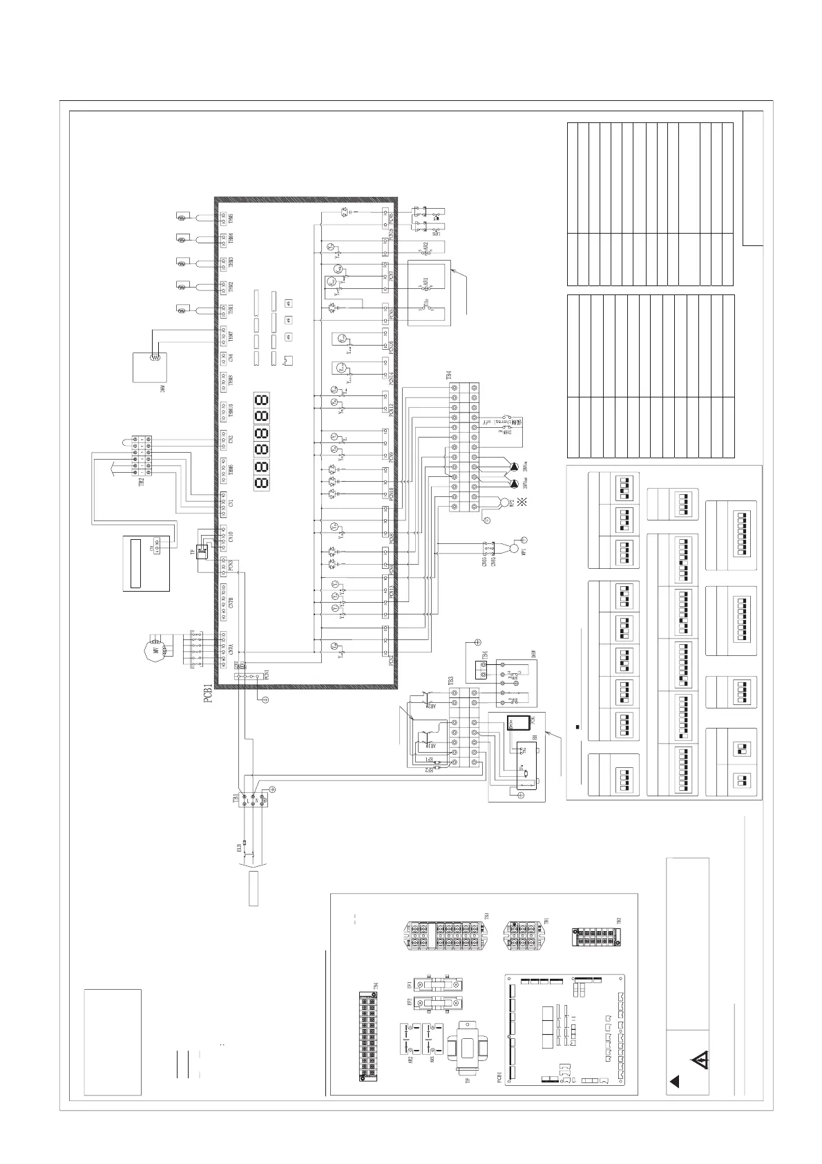
electric wiring diagram
NL
12 3 4
56
12 3 4
5
6
WN
M
M
43424140393837363534333231
WLTcoHNHLN1
L1
8765123
OFF
ON
48765123
OFF
ON
4
1
23
OFF
ON
41
23
OFF
ON
41
23
OFF
ON
4
DSW3
(80)
1
23
OFF
ON
4
(90)
1
23
OFF
ON
4
(112)
1
23
OFF
ON
4
(140)
1
23
OFF
ON
41
23
OFF
ON
4
(160)
1
23
OFF
ON
4
DSW1
3937
PCN10 PCN4
CN5
CN2
CN1
CN3
CN4
CN7A
CN7B
CN8
C
N
10CN
1
9
DSW1 DS
W2 DSW3 DSW4
DSW5
DSW6
DSW7
D
SW8 DSW9
EF1
EF
R
1
EFR2
PCN1PCN3
PCN2PCN8
PCN5PCN6
PCN7PCN9 PC
N
1
2
P
C
N1
3
PCN14
P
CN
1
5
PCN16
PS
W
1
SE
G3SEG2SEG1
THM1
THM2 THM4
THM5
THM3 THM6
THM8
THM10
TP1
JP1
JP2
THM7
C
N6
8.8. 8.8. 8.8.
PSW2 PSW
3
8
7
65
1
23
OFF
ON
4
8
7
65
1
23
OFF
ON
4
123
OFF
ON
4
1
2
OFF
ON
1
2
OFF
ON
DSW6
1
23
OFF
ON
4
DSW5
8765123
OFF
ON
48765123
OFF
ON
48765123
OFF
ON
4
☆
ELB
H7B02163A
:
DSW1 DSW2 DSW3
DSW4
DSW5 DSW7 DSW8 DSW9
PSW1 PSW2 PSW3
SEG3SEG2
TP1
SEG1
☆
☆☆ ☆☆
☆
Factory wiri
Earth wire
Leakage protector must be
mounted when wiring is made.
Parts are selected by function.
Electrical control box of indoor unit
ʽ
Warning
When electrical parts are checked, the
operation switch must be set as OFF, and
power supply is cut off.
Technique requirements:
1. All on-site wiring and equipments must be conforming to local regulations.
wired controller
outdoor unit
communication
external input power
water tank sensor
effluent
sensor
influent
sensor
plate heat
exchanger
effluent
sensor
air
tube
liquid
tube
sensor
Only auxiliary
motor type
is provided.
Only auxiliary
motor type
is provided.
dial switch
setting table
side means dial switch location
DSW2 model capacity setting
DSW4 unit special function setting
factory setting
factory setting
factory setting
factory setting factory setting factory setting factory setting
water temperature
sensor makes invalid correction.
Goal Pd correction 1
(increase goal Pd)
increase opening
ratio of electric heating
Goal Pd correction 2
(increase goal Pd)
factory setting
factory setting
electric heating
forced OFF
water pump
forced ON
replace
communication fuse
DSW8 refrigerant system setting
DSW9 reserve function
DSW7
Mark Name
AR1, AR2 Relay
CMC AC contactor
CN
1-10
Terminal block
CN
60
Terminal block
DHW Water tank
DHW
THe1
, DHW
THe2
, Water tank temperature controller
DSW
1-5, 7-9
Dial switch
EFR1, EFR2 Fuse ( on the board)
EF1, EF2 Fuse
EH Water module electric heating
LWPS Low water pressure switch
MV Electrical expansion valve
PCB1 Circuit board
Mark Name
PCN
1-16
Terminal block
TB
1,2,3,4
Terminal strip
TF Transformer
TFe Electric heating fuse
The Electric heating temperature controller
WFS Water flow switch
WP1 Built-in water pump in water module
WP2 External water pump (assembled on site)
Y
1
-Y
3
, Y
20A
, Y
20B
Relay (on the board)
Y
boiler
, Y
solar
, Y
52C1
,
Y
52C2
, Y
DH
Relay (on the board)
Y
A
, Y
PR
, Y
E2
, Y
20L
Relay (on the board)
3WV
DHW
Water tank three-way valve
3WV
FH
Floor heating three-way valve
Only auxiliary motor
type is provided.
10.2.3 Electrical Connection Diagram
power source



 To Next Page