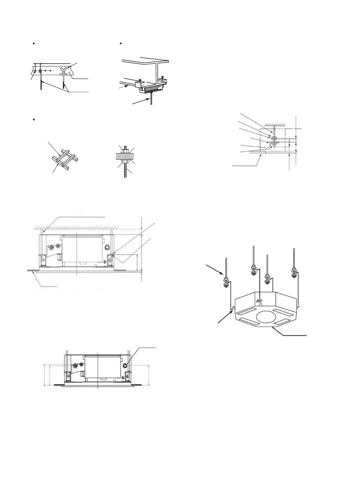
Fig. 4.4 Mounting the Suspension Bolts
4.3.2 Connection Points of Suspension Bolts and Pipes
4.3.3 Mounting the Indoor Unit
Mount the indoor unit as shown in Fig. 4.4.
Mount field-supplied parts
Suspension bolt 4-M10 or W3/8
Nut 8-M10 or W3/8
Washer 8-M10 or W3/8
(1) Mount nuts and washers to the suspension bolts.
Fig. 4.8 Mounting the Indoor Unit
For Concrete Slab
For Steel Beam
150 to 160mm
Screw in
(100 to 150kg)
Concrete
Suspension Bolt
(W3/8 or M10)
Fixing Point
, Beam
Suspension Bolt
(W3/8 or M10)
For Wooden Beam
Suspension
Wooden Rib
(60mm to 90mm
lumber)
Wooden Beam
(2) Lift the indoor unit by hoist, and do not
put any force on the water pan.
(3) Secure the indoor unit using the nuts and
washers.
Note: If a false ceiling has already been
installed, be sure to complete all piping and
wiring works inside the ceiling before
hooking-up the indoor unit.
Nut
Square Washer
Suspension Bolt
Nut
Square Washer
Suspension Bolt
Suspension Bracket
Water Pan
Fig. 4.7 Mounting Nuts and Washers
Suspension Bolt (Field Supplied)
Nut (Field Supplied)
*
Insulating Washer
(Accessory)
Bracket (for Fixing Indoor Unit)
Washer (Accessory)
Nut (Field Supplied)
Surface of Ceiling
Approx. 50
Approx. 50
*
Mount the washer with its insulating surface
facing down
Fig. 4.5 Mounting Suspension Bracket
Fig. 4.6 Indoor Unit and Air Panel
167 (Liquid Pipe)
157 (Gas Pipe
)
Drain Pipe
Washer
(Accessory)
Nut
(Field-Supplied)
Location of 4 Suspension Bolts
M10 or W3/8
(Field-Supplied)
Surface of Ceiling
Confirm the distance between the bottom surface of indoor unit and
the surface of ceiling.
*
3
Ĺ
mm
mm
160
mm
110



 To Next Page