This document describes the Hisense inverter-driven multi-split air conditioner (heat pump), specifically focusing on its operation, installation, and maintenance.
Function Description
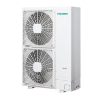
The Hisense heat pump air conditioner is designed for standard air conditioning, providing both cooling and heating functions. It is an inverter-driven multi-split system, meaning it can connect multiple indoor units to a single outdoor unit, offering flexible climate control for various spaces. The system is designed to operate within specific temperature ranges for optimal performance.
Important Technical Specifications
Model Compatibility:
The manual covers various models, including:
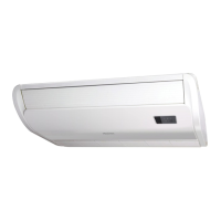
- Ceiling Type: AVD-07UX2SA L(H), AVD-09UX2SA L(H), AVD-12UX2SA L(H), AVD-14UX2SA L(H), AVD-17UX2SA L(H), AVD-18UX2SA L(H), AVD-22UX2SA L(H), AVD-24UX2SB L(H), AVD-27UX2SC L(H), AVD-30UX2SC L(H), AVD-38UX2SC L(H), AVD-48UX2SD L(H), AVD-54UX2SD L(H).
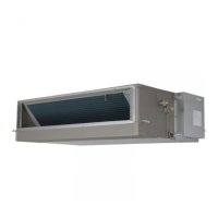
- Ducted Type: AVD-07UX2SA L(H), AVD-09UX2SA L(H), AVD-12UX2SA L(H), AVD-14UX2SA L(H), AVD-17UX2SA L(H), AVD-18UX2SA L(H), AVD-22UX2SA L(H), AVD-24UX2SB L(H), AVD-27UX2SC L(H), AVD-30UX2SC L(H), AVD-38UX2SC L(H), AVD-48UX2SD L(H), AVD-54UX2SD L(H).
Refrigerant: The system uses R410A refrigerant.
Power Supply: The power supply voltage should be within ±10% of the rated voltage.
Control Circuit Fuse Capacity: 5A.
Evaporator Fan Motor Thermostat: Cut-Out at 130±5°C, Cut-In at 83±15°C.
Freeze Protection Thermostat: Cut-Out at 0°C, Cut-In at 14°C.
Thermostat Differential: 2°C.
Maximum Current (for various models):
- 07-09: 1.1A
- 12-14: 1.5A
- 17-22: 1.6A
- 24: 1.9A
- 27-38: 3.0A
- 48-54: 4.2A
Operation Temperature Range:
- Cooling Operation:
- Indoor: 32 DB/23 WB (Maximum), 21 DB/15 WB (Minimum)
- Outdoor: 43 DB (Maximum), -5 DB (Minimum)
- Heating Operation:
- Indoor: 27 DB (Maximum), 15 DB (Minimum)
- Outdoor: 15 WB (Maximum), -15 WB*1 (Minimum)
- *1: -10 WB ~ -15 WB: Operation Control Range
Piping Dimensions (Gas Piping / Liquid Piping):
- 07-14: Ø12.7 (1/2) / Ø6.35 (1/4)
- 17-18: Ø15.88 (5/8) / Ø6.35 (1/4)
- 22-30: Ø15.88 (5/8) / Ø9.53 (3/8)
- 38-54: Ø19.05 (3/4) / Ø9.53 (3/8)
Tightening Torque for Flare Nut:
- Ø6.35mm: 20 N.m
- Ø9.53mm: 40 N.m
- Ø15.88mm: 80 N.m
- Ø19.05mm: 100 N.m
Drain Piping: Polyvinyl chloride pipe with a 32mm outer diameter. Must be performed with a DOWN-SLOPE pitch of 1/25 to 1/100.
Usage Features
Remote Control: The system is controlled via a remote control switch. Up to 16 indoor units can be controlled by one remote control switch.
Temperature Setting: The temperature can be adjusted using the TEMP switch, increasing by 1 degree per press. The minimum setting is 17°C, and the maximum is 30°C.
Multi-Unit Control: The system supports controlling multiple indoor units (up to 16) with a single remote control.
Automatic Control: The system has automatic control features, including a three-minute guard (enforced stoppage) to protect the compressor, a three-minute elapsed function for delayed starts, and an oil return operation.
Frost Prevention: During cooling operation, the unit prevents frost formation on the indoor heat exchanger.
Defrosting Operation: During heating operation, the unit performs automatic defrosting to melt ice on the outdoor heat exchanger.
DIP Switch Settings: The indoor unit PCB is equipped with rotary switches and dip switches for setting the unit number, refrigerant cycle number, and capacity code. These settings are crucial for the unit's operation and must be configured correctly before use.
Maintenance Features
General Check:
- Electrical Components: Ensure all field-selected electrical components (main power switches, circuit breakers, wires, conduit connectors, and wire terminals) comply with "Technical Catalog I" and National Electrical Code (NEC).
- Power Supply Voltage: Verify the power supply voltage is within ±10% of the rated voltage.
- Electrical Wires: Check the capacity of electrical wires to prevent voltage drop.
- Ground Wire: Ensure the ground wire is connected.
- Main Switch: Install a multi-pole main switch with a space of 3.5mm or more between each phase.
- Refrigerant Leakage: Regularly check for refrigerant leakage, which can cause difficulty with breathing due to insufficient air. If leakage occurs, turn OFF the main switch and contact your service contractor.
- Air Filter: Check if the air filter is clogged with dust.
- Drain Water Overflow: If drain water overflows from the indoor unit, stop operation and contact a contractor.
Troubleshooting:
- No Cooling/Heating: Check for airflow obstructions, excessive heat sources, clogged air filters, open doors/windows, and ensure the temperature condition is within the operation range.
- Smells from Indoor Unit: Clean the air filter and panels or ensure good ventilation.
- Sound from Deforming Parts: Abrading sounds during start/stop are normal due to thermal deformation of plastic parts.
- Steam from Outdoor Heat Exchanger: Steam during defrosting is normal.
- Dew on Air Panel: Dew can form under high humidity conditions (above 27°C/80% R.H.).
- Refrigerant Flow Sound: Sound from refrigerant flow during start/stop is normal.
Installation and Handling:
- Safety Precautions: Do not perform installation, piping, or electrical wiring without referring to the installation manual. Ensure the ground wire is securely connected and use fuses of specified capacity.
- Refrigerant Handling: Use R410A refrigerant. Do not charge oxygen, acetylene, or other flammable/poisonous gases into the refrigerant cycle. Use compressed air, nitrogen, or refrigerant for leakage tests.
- Piping Materials: Use clean copper tubes, free from dust and moisture. Blow the inside of tubes with nitrogen or dry air before connecting.
- Drain Piping Check: After drain piping and electrical wiring, check that water flows smoothly by pouring 2 to 2.5 liters of water into the drain pan.
- Electrical Wiring: Turn OFF the main power switch before electrical wiring work. Protect wires, drain pipe, and electrical parts from small animals. Tighten screws according to specified torque (M3.5: 1.2 N-m, M5: 2.0-2.4 N-m).
- ELB (Electric Leakage Breaker): Use an ELB to prevent electric shock or fire.
- Cable Routing: Run cables through conduit tubes and seal the ends.
- DIP Switch Setting: Ensure DIP switches are set correctly according to the manual. If set incorrectly, the unit will not function. Always turn OFF the power source before setting DIP switches.
Disposal: This product should not be disposed of with household waste. It should be recycled responsibly through return and collection systems or by contacting the retailer.
Hisense emphasizes continuous improvement in design and performance, reserving the right to vary specifications without notice. This manual is considered a permanent part of the air conditioning equipment and should remain with it.