4.2 Initial Check
To avoid any corrosive action to the heat
exchangers, do not install the indoor unit in
an acid or alkaline environment.
4.3 Installation
4.3.1 Opening of False Ceiling and Suspension Bolts
Install the indoor unit in a space for easy operation
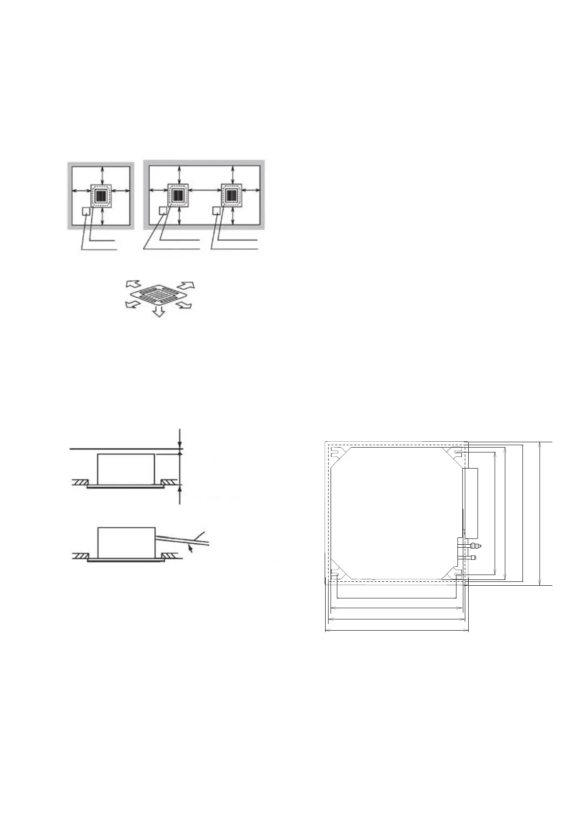
and maintenance as shown in Fig. 4.1.
Provide a service access door near the unit
piping connection area on the ceiling.
Check to ensure that the ceiling is strong
enough to hang the indoor unit.
Check if the ceiling surface is flat for the air
panel installation.
(1) Select appropriate location and direction for installation
of indoor unit, and determine its location. Pay careful
attention to the space for the piping, wiring and
maintenance.
(2) Cut out the area for the indoor unit in the false ceiling
Fig. 4.1 Space around Indoor Unit
The indoor unit must be installed at an appropriate
location so that the indoor temperature can be evenly
distributed.
There should be no obstruction of air flow at the vent.
Select the installation location as follows:
(A) Minimum Space
(B) Down Slope
Pitch of Drain Pipe: 1/25~1/100
Do not install the indoor unit in a machinery
shop or kitchen where vapor from oil or its mist
flows to the indoor unit.
Once the oil deposits on the heat exchanger, it
may impair the performance of indoor unit and
cause damage to plastic parts therein.
Pay attention to the following points when the
indoor unit is installed in a hospital or other
facilities where there are electronic waves
from medical equipment, etc.
(A) Do not install the indoor unit where the
electromagnetic wave is directly radiated to the
electrical box, remote control cable or remote
control.
(B) Install the indoor unit and components as far as
practical or at least 3 meters from the
electromagnetic wave radiator.
(C) Install the remote control switch in an iron box.
Arrange the remote control cable in an iron
tube. Ground the iron box and iron tube.
(D) Install a noise filter when the power supply emits
harmful noises.
Fig. 4.2 Installation Location of Indoor Unit
Fig. 4.3 Opening of False Ceiling and Suspension
Bolts
(3) Ensure that the ceiling is horizontally level;
otherwise, proper drainage flow would be impossible.
(4
) Strengthen the opening parts of the ceiling.
(5) Mount suspension bolts, as shown in the figure.
10~20 mm
245 mm
Indoor Unit Height in Ceiling
Drain Pipe
1/25~1/100 Down Slope
and install suspension bolts, as shown in Fig. 4.2.
1500mm
Min.
1500mm
Min.
1500mm
Min.
1500mm
Min.
1500mm
Min.
3000mm Min.
1500mm
Min.
1500mm
Min.
1500mm
Min.
1500mm
Min.
1500mm
Min.
Piping Connection
Service Access Door
Piping Connection
Service Access Door
Piping Connection
Service Access Door
Distance from Wall Side
500mm Min.
100mm Min.
100mm Min.
500mm Min.
1000mm Min.
Piping Connection
Service Space
mm
2
530 (Dimension of Suspension Bolts)
570(Unit Size)
575~595(Dimension of Opening )
530 (Dimension of Suspension Bolts)
570 (Unit Size)
575~595 (Dimension of Opening )
620 (Dimension of Panel )
620 (Dimension of Panel )



 To Next Page