13.4 Procedure of Checking Other Main Parts
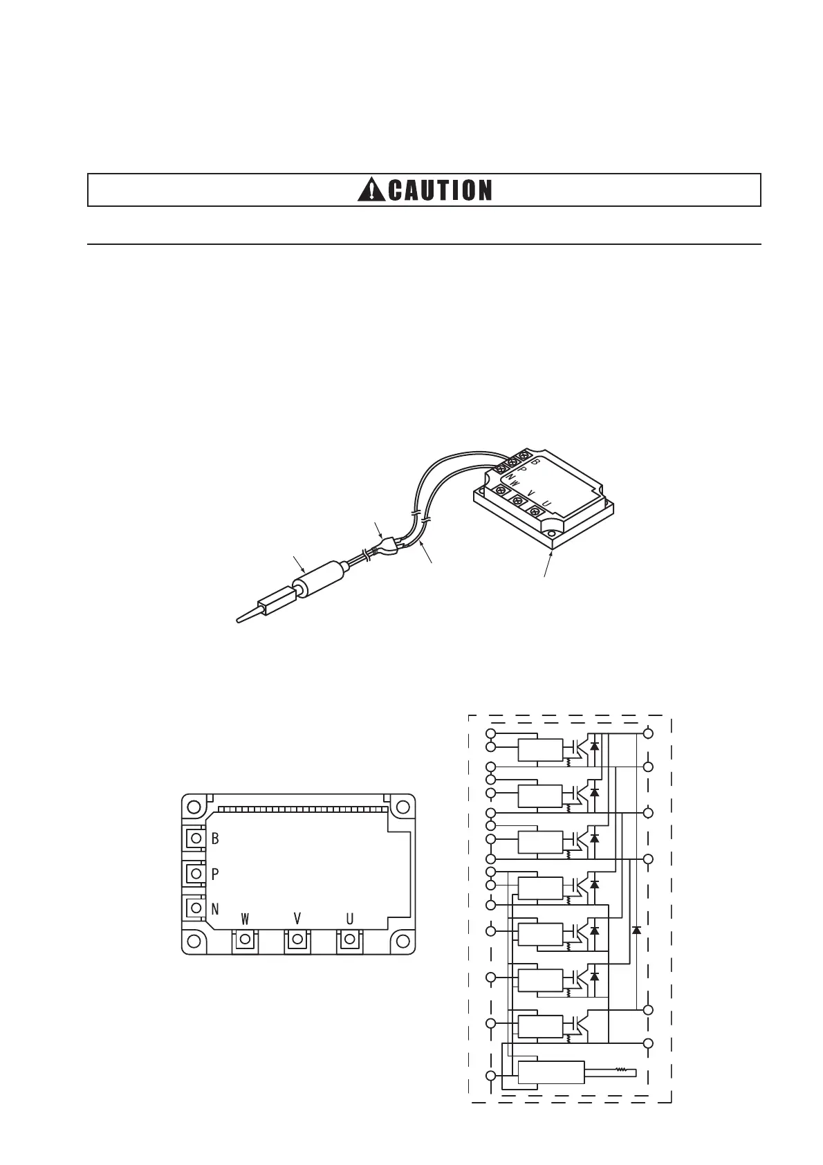
(1) High Voltage Discharge Work for Replacing Parts
Solder Bit
Connecting Wires
Plug
Transistor Module (IPM)
(2) Checking Method of Transistor Module (IPM)
Outer Appearance and Internal Circuit of Transistor Module
Drive Circuit
Over Heating
Protection Circuit
Sensor
B
N
P
U
U
W
Drive Circuit
Drive Circuit
Drive Circuit
Drive Circuit
Drive Circuit
Drive Circuit
P >
(a) Turn OFF the main switches and wait for three minutes. Check to ensure that no high voltage
exists. If LED201 is ON after start-up and LED201 is OFF after turning OFF power source, the
voltage will decrease lower than DC50V.
(b) Connect connecting wires to an electrical solder bit
(c) Connect the wires to terminals, P and N on IPM. => Discharging is started, resulting in hot solder
bit. Pay attention not to short-circuit between terminal P and N.
(d) Wait for 2 or 3 minutes and measure the voltage once again. Check to ensure that no voltage is
charged.
t is high voltage discharge work to avoid an electric shock.
Perform h
< rocedure



 To Next Page