7
AV3000 AVC Unit Service Manual
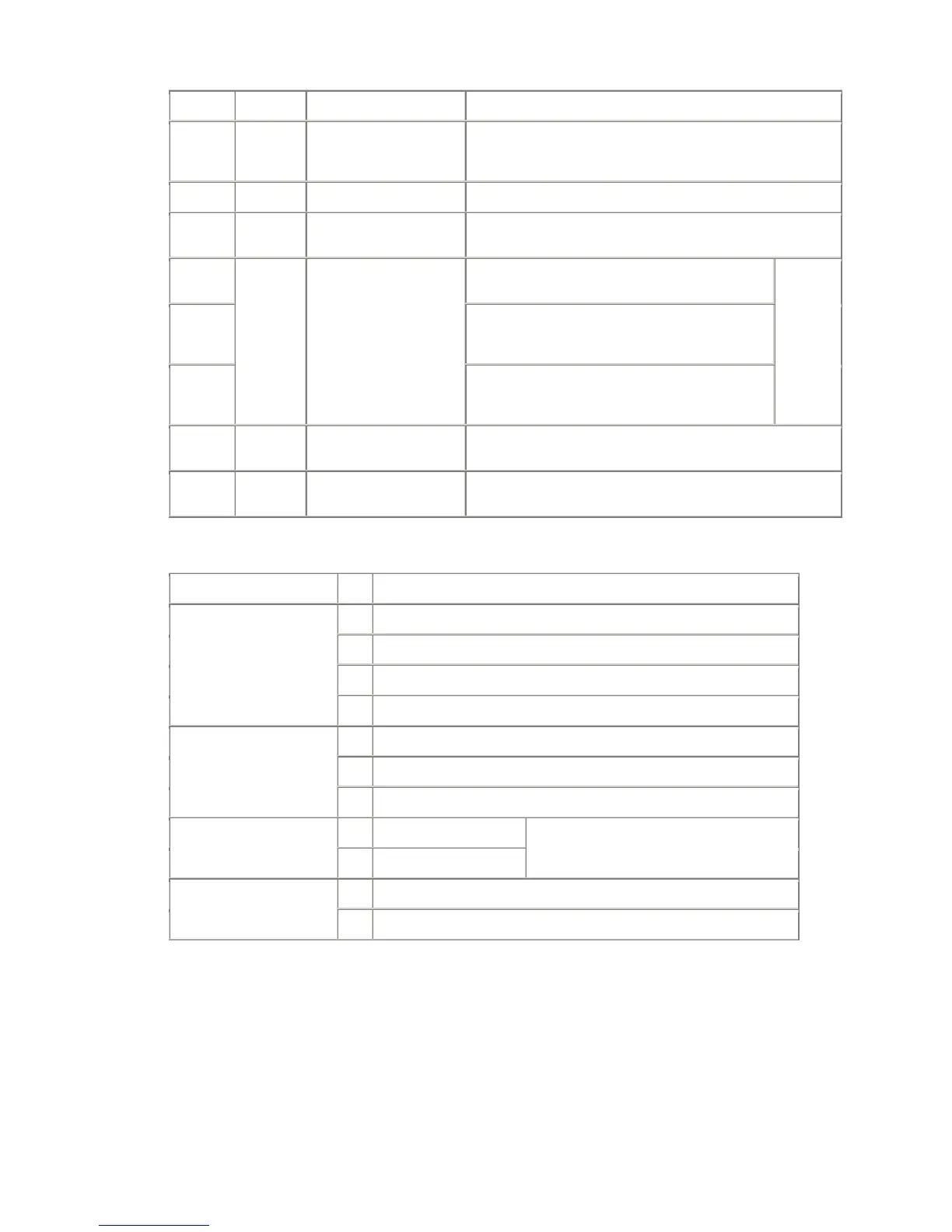
CRN Type Description
Remarks
IC08 TA1370
Sync separation for
Component (progressive)
input
Supply voltage: +9V at pin 11
Control by I
2
C, SDA at pin 21 and SCL at pin 22
XC01 Crystal 50KHz
IC02/IC03 TA1287 YUV/RGB switch
Supply voltage: +9V at pin 16
Control by DC voltage at pins 9/10/11 and matrix at pin 16
IC04
Audio switch, main L/R or AV4 (components input)
L/R. main L/R comes from MSP3410 audio switch
IC05
Video switch, Front video or AV4 (in case of YCbCr
normal components), which is connected to
TDA9321 for sync separation
IC06
BU4066 Analogue switch
Audio switch, Centre sound or AV4 (components
input) L/R. Output goes to IC04 to switch another
audio input
supply
voltage:
+9V at pin
14
IC07 BU4053
Analogue Switch for Sub-
video
Supply voltage: +9V at pin 16
IC09 M62320FP I/O expanders
Supply voltage: +5V at pin 13
Control by I
2
C, SDA at pin 3 and SCL at pin 2
4.4.1. TA1287
YUV/RGB switch (IC02/IC03)
CRN Remarks
IC02 YUV: Main signal
IC03 YUV: from IC02
YUV: at pin 1/2/3, Y:1 V
p-p
(incl. sync), UV:0.3Vp-p
Input:
RGB: at pin 6/7/8, 0.7Vp-p
IC02 Connect to IC03
IC03 Connect to FC4 through buffers
Output:
YUV: at pin13/14/15, Y:1 V
p-p
(incl. sync), UV:0.3Vp-p
IC02 0V: through Matrix control of RGB input:
IC03 Always 1.6V:RGB > YUV
(YUV can also input.
In this case, matrix control should be through)
IC02 0V: external (Components input) Control:
IC03 0V: Video