EasyManua.ls Logo

Hitachi P50T01U User Manual

Hitachi P50T01U
77 pages
To Next Page IconTo Next Page
Page #1 background imageLoading...
Page #1 background image
CAUTION:
Before servicing this chassis, it is important that the service technician read the “Safety
Precautions” and “Product Safety Notices” in this service manual.
ATTENTION:
Avant d’effectuer l’entretien du châassis, le technicien doit lire les «Précautions de sécurité»
et les «Notices de sécurité du produit» présentés dans le présent manuel.
VORSICHT:
Vor Öffnen des Gehäuses hat der Service-Ingenieur die „Sicherheitshinweise“ und „Hinweise
zur Produktsicherheit“ in diesem Wartungshandbuch zu lesen.
SERVICE MANUAL
MANUEL D'ENTRETIEN
WARTUNGSHANDBUCH
Data contained within this Service
manual is subject to alteration for
improvement.
Les données fournies dans le présent
manuel d’entretien peuvent faire l’objet
de modifications en vue de perfectionner
le produit.
Die in diesem Wartungshandbuch
enthaltenen Spezifikationen können sich
zwecks Verbesserungen ändern.
SPECIFICATIONS AND PARTS ARE SUBJECT TO CHANGE FOR IMPROVEMENT
PlasmaTV
May 2007
SM016
P50T01E
P50T01U
P50TP01E
P50TP01U
P42T01E
P42T01U
P42TP01E
P42TP01U
Question and Answer IconNeed help?

Do you have a question about the Hitachi P50T01U and is the answer not in the manual?

Hitachi P50T01U Specifications

General IconGeneral
BrandHitachi
ModelP50T01U
CategoryPlasma TV
LanguageEnglish

Summary

CAUTION FOR SAFETY

Safety Symbols and Instructions

Explains safety symbols and provides instructions for safe repair procedures.

Preventing Electric Shock

Details on handling high voltage parts and disconnecting power to prevent electric shock.

Component and Wiring Safety

Guidance on using recommended components and maintaining wiring style for safety.

PRECAUTIONS

Monitor Cleaning Procedures

Instructions for cleaning the screen and cabinet, including what to avoid.

Environmental Disposal Information

Guidance for users in EU countries on proper disposal of electronic equipment.

1. Features

High-Definition Plasma Panel

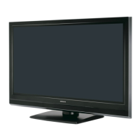
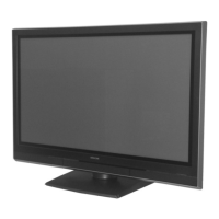
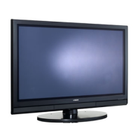
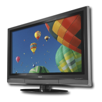
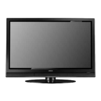
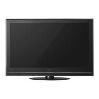
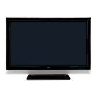
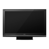
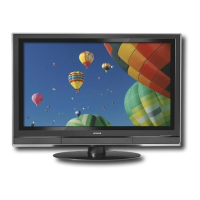
Describes the large-screen plasma panel and its resolution capabilities.

Digital Processor and Signal Handling

Details the digital processor's ability to handle various inputs for enhanced image quality.

User Interface and Connectivity

Covers the remote control, on-screen display, and AV/HDMI input terminals.

Media and Swivel Features

Information on the SD card slot and the Power Swivel feature for screen adjustment.

Digital Terrestrial Television Broadcasting

2. Specifications

3. Service points

Lead-Free Solder Servicing

Guidelines for servicing with lead-free solder, including tools and techniques.

Power Supply Voltage Adjustment

Procedure for readjusting power supply voltages (Va, Vs) after component replacement.

4. Component names

Main Unit Component Identification

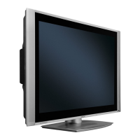
Identifies major components of the TV's main unit, front, and rear panels.

[Remote control]

Remote Control Operation Guide

Explains the function of each button on the remote control for TV operation.

[Terminal Positions]

External Connection Guide

Illustrates terminal locations and provides steps for connecting external equipment.

5. Adjustment

Adjustment Mode Operations

Activating, changing data, and resetting modes like Memory Init and Factory Reset.

Power Supply Voltage Adjustment (Vs/Va)

Procedure for adjusting Vs and Va voltages on the power unit.

Video Signal Amplitude Adjustment

Steps for adjusting RGB amplitude for Composite and Component inputs.

Video Colour Temperature Adjustment

Adjusting colour temperature to Cool, Normal, Warm, and B&W settings.

6. Troubleshooting

Basic Diagnostics and Burn-in Mode

Using LED status, burn-in mode, and power flowcharts for initial troubleshooting.

Picture Troubleshooting Flowcharts

Guides for diagnosing and resolving picture-related problems based on input signal types.

Sound Troubleshooting

Flowcharts for identifying and resolving sound problems for various inputs.

7. Self-Diagnosis Function

PDP Panel Failure Diagnosis

Self-diagnosis of PDP panel failures indicated by power indicator light blinks.

Digital Module Self-Diagnosis and Codes

Entering the digital module's self-test and understanding error codes.

8. Block diagram

9. Connection diagram

10. Wiring diagrams

11. Disassembly diagrams

13. Circuit diagrams

Signal Waveform Analysis

Visual representations of critical signal waveforms for troubleshooting.

Related product manuals