---------------------------------
LCD-IV
Timer/Counter Block Diagram
is
shown in Figure 21. 5-bit
divider divides the crystal oscillation (32.768kHz)
by
32 and
generates clocks
of
1,024Hz in the crystal oscillation mode.
It does
not
stop in the halt state. Prescaler divides the system
clock (instruction frequency) or
1,024Hz clock by 64 and
generates overflow output pulse
of
"Instruction frequency/
64Hz"
or
16Hz.
In
the crystal oscillation mode, it does not
stop during halt state. The input
of
the 4-bit counter
is
over-
flow output pulse
of
the pre scaler or a pulse
of
INTI terminal.
Input selection
is
determined by CF state. Data can
be
ex-
changed between the counter and bus by L TI,
LT
A or
LAT
instruction. TF
is
a flip-flop which masks the interrupt
of
timer/counter.
The timer
is
operable in 2 modes (timer mode and counter
mode) depending on what to count, and the mode
is
selected
by programs.
•
TimerMode
The 4-bit counter counts prescaler overflow output pulses.
One
of
the following two can be selected
as
the prescaler count
clock by the
mask
option.
1.
System clock (Instruction frequency)
2.
1,024Hz clock (Crystal oscillation for timer
is
selected.)
...
Clock obtained by dividing the crystal oscillation (32.768kHz)
for timer by 32.
Crystal oscillator
is
constructed between D
Internal halt state
terminals
of
DI4
and
DIS
:
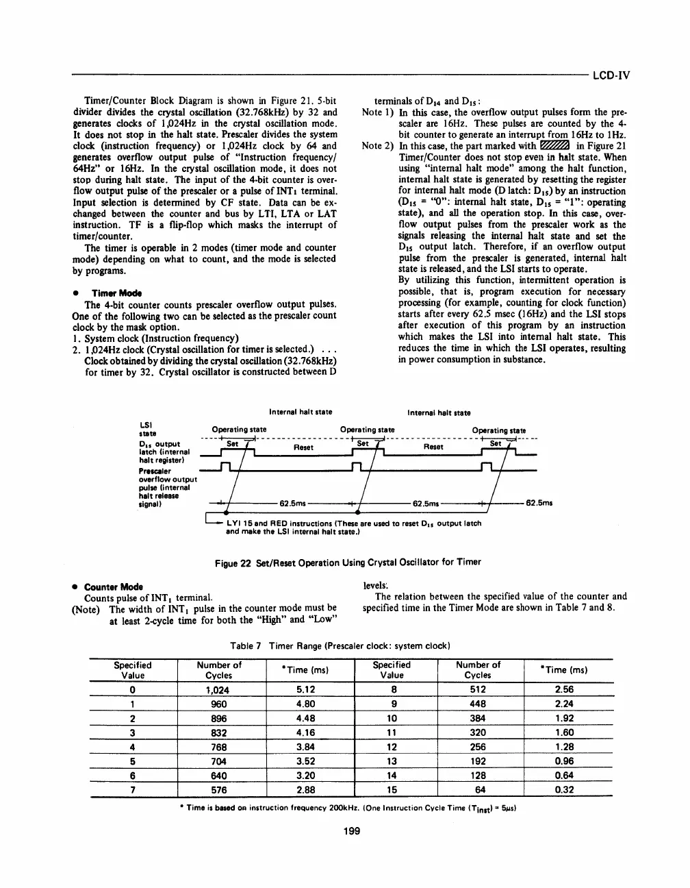
Note 1)
In this case, the overflow output pulses form the pre-
scaler
are
16Hz. These
pulses
are counted by the
4-
bit counter to generate an interrupt from 16Hz to 1
Hz.
Note 2) In this case, the part marked with
~
in Figure
21
Timer/Counter does not stop even in halt state.
When
using "internal halt mode" among the halt function,
internal halt state
is
generated
by
resetting the register
for internal halt mode
(0
latch: 0
15
)
by
an instruction
(D15
=
"0":
internal halt state, 015 = "1
":
operating
state), and
aU
the operation stop. In this case, over-
flow output pulses from the pre scaler work
as
the
signals releasing the internal halt state and set the
DIS
output latch. Therefore,
if
an
overflow output
pulse from the pre scaler
is
generated, internal halt
state
is
released, and the
LSI
starts
to
operate.
By
utilizing this function, intermittent operation
is
possible, that is, program execution for necessary
processing (for example, counting for clock function)
starts after every 62.5 msec (16Hz) and the
LSI
stops
after execution
of
this program by
an
instruction
which makes the
LSI into internal halt state. This
reduces the time in which
the
LSI
operates, resulting
in
power consumption
in
substance.
I nternal halt state
LSI
Operating state Operating state Operating state
stata
Oil
output
latch (internal
hal
t
regi
ster I
--
--+-s;t=t- ---
--
-
-~e~;t-
- - - - - -
--
- - - - -
-~e~;t--
- - - - -
~-----
Presc:aler
overflow
output
pulse (internal
halt release
signa
II
-'-+----62.5ms
-----+-I-----62.5ms
----1--1---
62.5ms
• Counter Mode
L V I
15
end R
ED
instructions (These are used to reset
DIS
output
latch
and make the
LSI
internal halt state.1
Figue 22 Set/Reset Operation Using Crystal Oscillator
for
Timer
levels~
Counts pulse
of
INT I terminal.
(Note) The width
of
INT I pulse
in
the counter mode must
be
at least 2-cycle time for both the "High" and "Low"
The relation between the specified value
of
the counter and
specified time
in
the Timer
Mode
are shown
in
Table 7 and 8.
Table 7 Timer
Range
(Prescaler clock: system clock)
Specified Number
of
·Time
(ms)
Specified
Number
of
·Time
(ms)
Value
Cycles Value
Cycles
0
t,024
5.12
8
512 2.56
1
960
4.80
9
448
2.24
2 896
4.48
10 384
1.92
3 832
4.16
11
320
1.60
4
768
3.84
12
256
1.28
5
704
3.52 13 192
0.96
6
640
3.20
14
128
0.64
7
576
2.88 15 64
0.32
• Time
is
based
OR
instruction frequency 200kHz. (One Instruction Cycle Time
(Tin't
l
=
5~sl
199


 To Next Page
 Loading...


