HMCS404C--------------------------------------------------------------
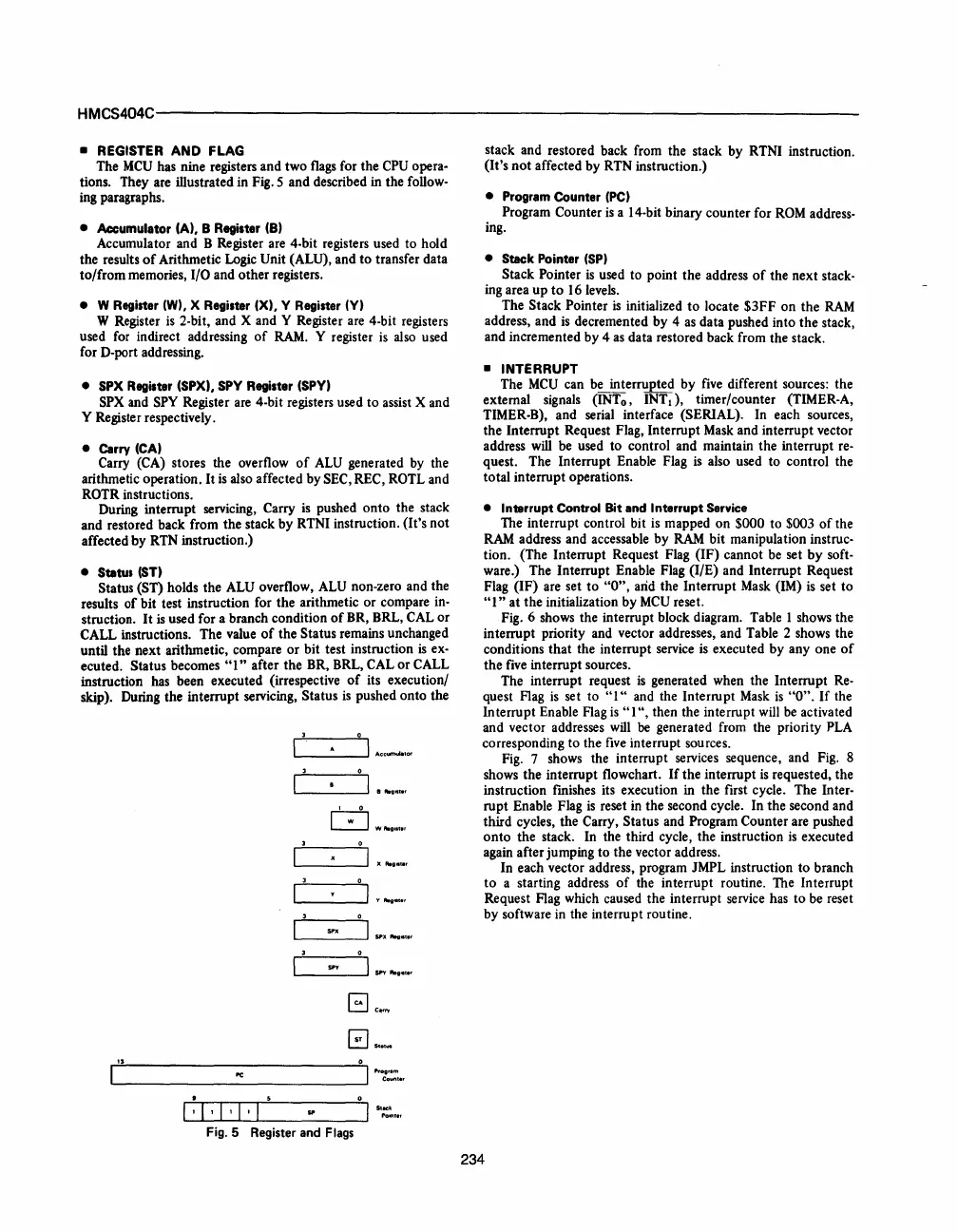
• REGISTER AND FLAG
The
MCU
has nine registers and two
flags
for the
CPU
opera-
tions. They are illustrated in Fig. 5 and described in the follow-
ing paragraphs.
• Accumulator (A), 8 Register (8)
Accumulator and B Register are 4-bit registers used to hold
the results
of
Arithmetic Logic Unit (ALU), and to transfer data
to/from memories,
I/O and other registers.
• W Register (W), X Register (X), Y Register
(Y)
W Register
is
2-bit, and X and Y Register are 4-bit registers
used
for
indirect addressing
of
RAM.
Y register
is
also
used
for D-port addressing.
• SPX Register (SPX),
Spy
Register (Spy)
SPX
and
Spy
Register
are
4-bit registers used
to
assist X and
Y Register respectively.
• Carry (CA)
Carry (CA) stores the overflow
of
ALU
generated
by
the
arithmetic operation. It
is
also affected by SEC, REC, ROTL and
ROTR instructions.
During interrupt servicing, Carry
is
pushed onto the stack
and restored back from the stack by RTNI instruction. (It's not
affected by
RTN
instruction.)
• Status
(ST)
Status (ST) holds the
ALU
overflow,
ALU
non-zero and the
results
of
bit test instruction for the arithmetic or compare
in-
struction.
It
is
used for a branch condition
of
BR, BRL,
CAL
or
CALL instructions. The value
of
the Status remains unchanged
until the next arithmetic, compare or bit test instruction
is
ex-
ecuted. Status becomes
"1"
after the BR, BRL, CAL or CALL
instruction has been executed (irrespective
of
its execution/
skip). During the interrupt servicing, Status
is
pushed onto the
L....-
___
....JI
..
cc
.......
,o<
L-
___
....J
SPY
"'gill.'
L....-
______________
....JI
..
o~:.,
......
1 :
.........
1
........
,
1_,
......
I'...l-I
___
--,I
s.;:~
.•
,
Fig. 5 Register and Flags
stack and restored back from the stack by RTNI instruction.
(It's not affected by RTN instruction.)
• Program Counter
(PC)
Program Counter
is
a 14-bit binary counter for
ROM
address-
ing.
• Stack Pointer
(SP)
Stack Pointer
is
used to point the address
of
the next stack-
ing area up
to
16
levels.
The Stack Pointer
is
initialized
to
locate $3FF on the
RAM
address, and
is
decremented by 4
as
data pushed into the stack,
and incremented by 4
as
data restored back from the stack.
• INTERRUPT
The
MCU
can
be
interrupted by
five
different sources: the
external signals (INTo,
INTd,
timer/counter (TIMER-A,
TIMER-B), and serial interface (SERIAL). In each sources,
the Interrupt Request Flag, Interrupt
Mask
and interrupt vector
address
will
be used to control and maintain the interrupt
re-
quest. The Interrupt Enable Flag
is
also used to control the
total interrupt operations.
• Interrupt Control Bit and Interrupt Service
The interrupt control bit
is
mapped on $000 to $003
of
the
RAM
address and accessable by
RAM
bit manipulation instruc-
tion. (The Interrupt Request Flag (IF) cannot be set
by
soft-
ware.) The Interrupt Enable Flag (I/E) and Interrupt Request
Flag (IF) are set
to
"0",
arid
the Interrupt
Mask
(1M)
is
set to
"1"
at the initialization by
MCU
reset.
Fig. 6 shows the interrupt block diagram. Table 1 shows the
interrupt priority and vector addresses, and Table 2 shows the
conditions that the interrupt service
is
executed by
anyone
of
the
five
interrupt sources.
The interrupt request
is
generated when the Interrupt
Re-
quest Flag
is
set to
"1"
and the Interrupt
Mask
is
"0".
If
the
Interrupt Enable Flag
is
"1
",
then the interrupt will be activated
and vector addresses
will
be
generated from the priority
PLA
corresponding to the
five
interrupt sources.
Fig.
7 shows the interrupt services sequence, and
Fig.
8
shows the interrupt flowchart.
If
the interrupt
is
requested, the
instruction fmishes its execution in the first cycle. The
Inter-
rupt Enable Flag
is
reset in the second cycle. In the second and
third cycles, the Carry, Status and Program Counter are pushed
onto
the stack. In the third cycle, the instruction
is
executed
again after jumping to the vector address.
In each vector address, program JMPL instruction to branch
to
a starting address
of
the interrupt routine. The Interrupt
Request Flag which caused the interrupt service has to be reset
by software
in
the interrupt routine.
234


 To Next Page
 Loading...


