---------------------------------------------------------------HMCS404C
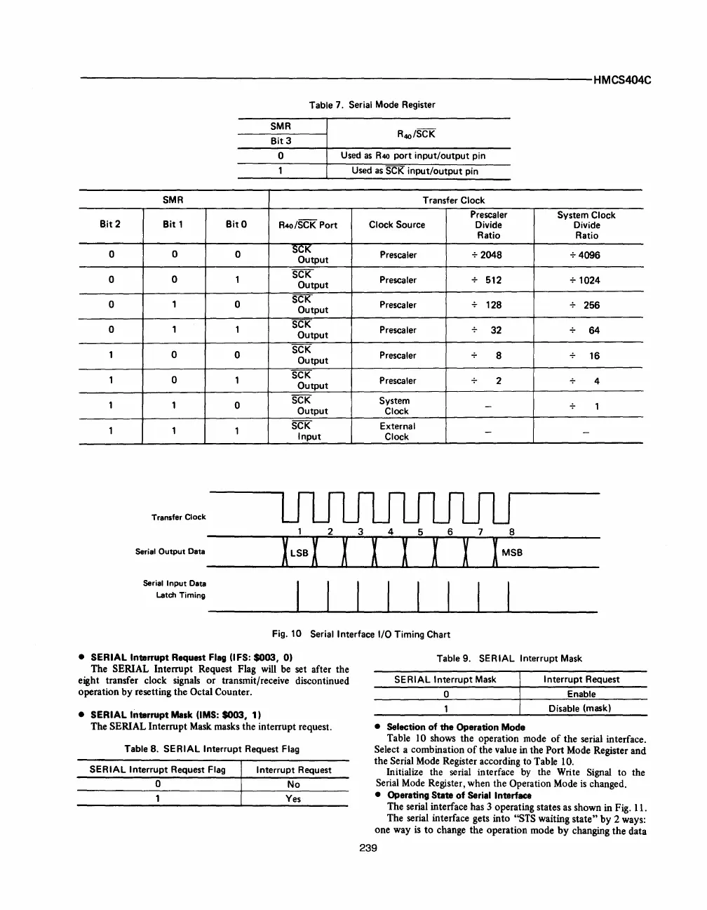
Table 7. Serial Mode Register
SMR
Bit3
o
Used
as
R40
port
input/output
pin
Used
as
SCK
input/output
pin
SMR
Transfer Clock
Prescaler
System Clock
Bit 2 Bit 1 BitO
R4o/SCK Port
Clock Source
Divide Divide
Ratio
Ratio
0
0
0
SCK
Prescaler
+2048
+4096
Output
0
0
1
SCK
Prescaler 512
+
1024
Output
0
1
0
SCK
Prescaler
128
256
Output
0 1 1
SCK
Prescaler
32
64
Output
1 0
0
SCK
Prescaler
8
16
Output
1 0
1
SCK
Prescaler
2 4
Output
1 1
0
SCK
System
-
1
Output
Clock
1 1
1
SCK
External
-
-
Input
Clock
Transfer Clock
Serial
Output
Data
Serial
Input
Data
Latch
Timing
I I I I I I I I
Fig. 10 Serial Interface I/O Timing Chart
• SERIAL Interrupt Request
Flag
(lFS: $003, 0)
The SERIAL Interrupt Request Flag will be set after the
eight transfer clock signals
or
transmit/receive discontinued
operation by resetting the
Octal Counter.
• SERIAL Interrupt
Mask
(lMS:
$003, 1)
The
SERIAL Interrupt
Mask
masks the interrupt request.
Table
8.
SERIAL Interrupt Request Flag
SERIAL Interrupt
Request Flag
Interrupt
Request
o
No
Yes
Table 9. SERIAL Interrupt Mask
SERIAL
Interrupt
Mask
Interrupt
Request
o
Enable
Disable
(mask)
• Selection
of
the Operation Mode
Table 10 shows the operation mode
of
the serial interface.
Select a combination
of
the value in the Port Mode Register and
the
Serial Mode Register according to Table 10.
Initialize the serial interface
by
the Write Signal to the
Serial
Mode
Register, when the Operation Mode
is
changed.
• Operating State
of
Serial Interface
The serial interface has 3 operating states as shown in Fig. 11.
The serial interface gets into
"STS waiting state" by 2 ways:
one way
is
to
change the operation mode
by
changing the data
239



 To Next Page