-------------------------------------------------------------HD614P080S
•
AC
CHARACTERISTICS
(Vee
=
4.5V
to
5.5V.
GND = OV.
Ta=
-20
to
+75°C.
if
not
specified.)
Symbol
Test
Value
Item
Pin
Name
Conditions
min
Unit
typ
max
Oscillation
Frequency
fose
OSC.,OSC
l
0.4
-
6.2
MHz
!S
..
'"
Instruction
Cycle
Time
tCYC
1.29
-
20
p.s
~
c
c,)
5l
Oscillator
Stabilization
GO
IX
tAC
OSC.,OSC
l
- -
20
ms
Time
~
Oscillation
Frequency
fose
OSC.,OSC
l
!::
..
0.4
-
6.2
MHz
U:S
u
'"
Instruction
Cycle
Time
tcyc
1.29
-
20
p.s
.-
c
Eo
~
:;
Oscillator
Stabilization
t,lIX
Time
tAC
OSC.,OSC
l
-
-
20
ms
External
Clock
Frequency
fcp
OSC.
0.4
-
6.2
MHz
~
External
Clock
"High"
tCPH
OSC.
70
-
-
tJ
Level Width
ns
0
U
External
Clock
"Low"
'iii
Level
Width
tCPL
OSC.
70
-
-
ns
E
!!l
External
Clock
Rise
Time
tcp,
OSC.
-
20
ns
x
-
w
External
Clock
Fall
Time
tCPf
OSC.
-
-
20
ns
Instruction
Cycle
Time
tCYC
1.29
-
20
p.s
fflIo
"High"
Level
Width
tlOH
INTO
2
-
-
tcyc
INTo
"Low"
Level
Width
tlOl
TNTo
2
-
-
tcyc
--
,
INTI
"High"
Level Width
tllH
lNTi
2 -
-
tcyc,
,
INTI
"Low"
Level
Width
till
INTi 2
-
-
tcyc
RESET
"High"
Level
Width
tRSTH
RESET
2
-
-
tcyc
Input
Capacitance
C
in
all
pins
f=1MHz
15
pF
Vin
=
OV
-
-
Reset
Fall
Time
tRSTf
-
-
20
ms
(Note
1)
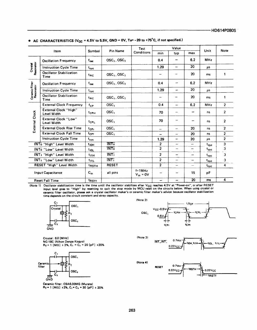
Oscillator stabilization time
is
the time until the oscillator stabilizes after
VCC
reaches 4.SV at "Power-on",
or
after RESET
input
level
goes to "High" by resetting to quit the stop mode by
MCU
reset on the circuits below.
When
using
crystal
or
ceramic filter oscillator, please ask a crystal oscillator maker's or ceramic filter maker's advice because oscillator stabilization
time depends on the circuit constant and stray capacity.
(Note
2)
asc,
tCPr
tCPf
Crystal: 6.0 [MHzl
(Note
3)
NC·18C (Nihon Denpa Kogyo)
Rf
= 1 [MOl ±
2%.
C,
= C.
'"
20 [pFl
±20%
C.
f,1::,ml~=
~C~
(Note
4)
OSC.
RESET
OSC.
GND
Ceramic filter: CSA6.00MG (Murata)
Rf·l
[MOl
±2%,
C.-
C.
·30
[pFl ±
20%
263
Note
1
1
2
2
2
2
2
2
3
3
3
3
4
4


 To Next Page
 Loading...



