18
English
(1) Right angle cutting
Loosen the three 5 mm machine screws, then secure the left side table insert and
temporarily tighten the 5 mm machine screws of both ends. Then fi x a workpiece
(about 7-7/8" (200 mm) wide) with the vise assembly and cut it off . After aligning the
cutting surface with the edge of the table insert, securely tighten the 5 mm machine
screws of both ends. Remove the workpiece and securely tighten the 5 mm center
machine screw. Adjust the right hand table insert in the same way.
(2) Left and right bevel angle cutting
Adjust the table insert in the manner shown in Fig. 8-b and Fig. 8-c following the same
procedure for right angle cutting.
CAUTION: After adjusting the table insert for right angle cutting, the
table insert will be cut to some extent if it is used for bevel
angle cutting.
When bevel cutting operation is required, adjust the table
insert for bevel angle cutting.
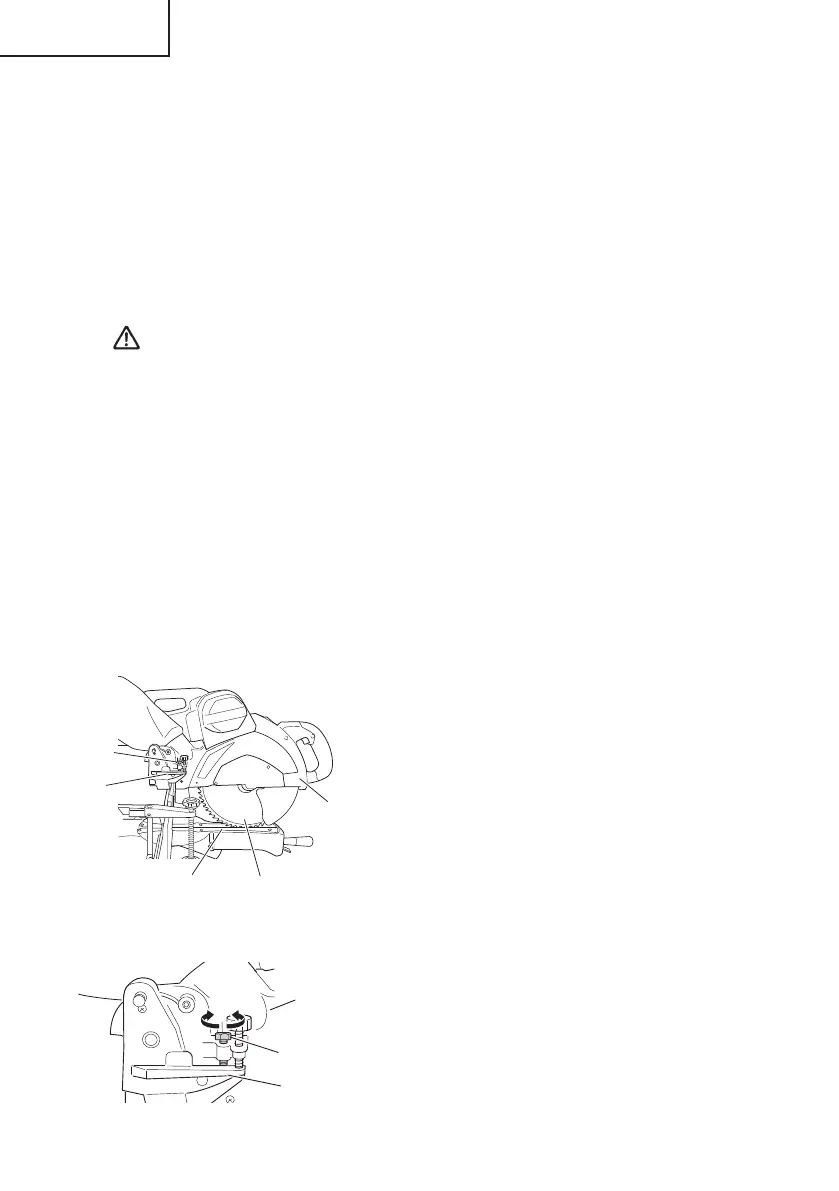
2. Checking the saw blade lower limit position
Check that the saw blade can be lowered 23/64" to 7/16" (9 mm to 11 mm) below the table
insert as shown in Fig. 9-a.
When you replace a saw blade with a new one, adjust the lower limit position so that the saw
blade will not cut the turntable or complete cutting cannot be done.
To adjust the lower limit position of the saw blade, follow the procedure (1) indicated below.
(Fig. 9-b)
Furthermore, when changing the position of a 8 mm depth adjustment bolt that serves as a
lower limit position stopper of the saw blade.
(1) Turn the 8 mm depth adjustment bolt,
change the height where the bolt head and
the hinge contacts, and adjust the lower
limit position of the saw blade.
NOTE: Confi rm that the saw blade is
adjusted so that it will not cut into
the turntable.
Gear case
8 mm depth
adjustment
bolt
Saw blade
Turntable
Fig. 9-a
Hinge
Fig. 9-b
8 mm depth
adjustment bolt
Turn
Hinge
Gear case
0000BookC12RSH2.indb180000BookC12RSH2.indb18 2016/03/0118:07:312016/03/0118:07:31
 Loading...