IF signal is sent to I001 pin 23 and 24 for demodulation. Fo
V STEREO mode, the demodulated
signals are sent for video and audio selection. For NICAM/A2 mode, the demodulated signals are sent for video
processing only.
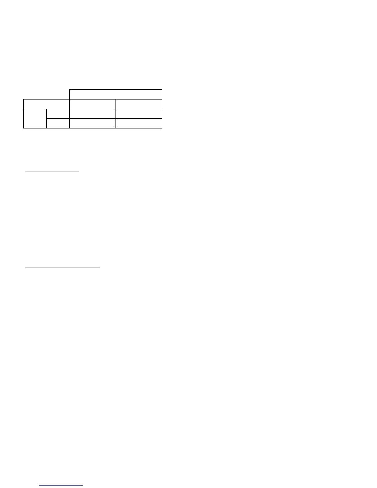
The composite video signals after demodulation are sent to a series of bandpass filters (X004 - X006) through
pin 38 of I001. The system selection is as follows
The selected RF video signal is sent to pin 40 of I001 and output AV terminal. The external video signal from input A
1 and 2 terminal also goes through pin 38 to output AV terminal. This is done by use of internal switch control
Video / Chroma
I401 select Video 1 or Video 2 signals and sent to pin 42 of I001. The video input signals (RF at pin 40, Video 1 an
Video 2 at pin 42) are selected using internal AV switch in I001 controlled by IIC bus. The selected video signals ar
processed with teletext. After color indentification and decoding, the color difference signals are matrixed with th
luminance signal to obtain the RGB signals. The RGB can be controlled by contrast and brightness and output at pi
51 - 53 to CRT PWB, in sequence with the OSD RGB
Internal sync separator and H/V oscillator of I001 produce H and V drive signals which are applied to deflectio
circuits for horizontal and vertical scanning
udio mode switching
For MONAURAL (without NICAM/A2) sound models, two audio switching is carried out. The RF audio signal afte
demodulation in I001 is output at pin 28 of I001 to pin 10 of I401. I401 perform audio selection using control sign
between the RF audio signal and external audio signal input (pin 8) of I401. The audio output at pin 6 of I401 is se
to output AV terminal.
The external audio input is also sent to pin 35 of I001 to perform the second audio switching with the RF audio sign
in I001. The selected audio signal goes through volume control before output at pin 44 of I001 to L(pin2) and R(pi
5) of I402. Amplification took place and output at L (pin12) and R (pin7) of I402 to the speakers
For NICAM/A2 sound models, the IF signal is input at pin 1 of X002 (saw filter) and output at pin 4 and 5 to pin 28 an
pin 29 of I001. After demodulation, the audio signal output at pin 35 to NICAM PWB (pin 2 of EN01) for NICAM proces
sing. The NICAM audio output at pin L (pin 10) and R (pin 11) of EN01 goes to SOUND PWB at pin 9 and 10 of EA01
For
V STEREO sound models, the audio signal is output at pin 44 of I001 and goes to SOUND PWB at pin 9 and 10
of EA01.
Audio input (L and R) from AV 1 And 2 terminal are input to pin 1 - 4 of EA01. Audio switching, volume comtrol, trebl
and bass are processed at IA01 (TDA9856). The L (pin 7) and R (pin6) output at EA01 goes to output AV terminal
The L (pin 12) and R (pin 11) at EA01 goes to I402 for amplification before sending to the speakers
High B/G, I, D/
- 9 -
Buffers
Q003
Signal output to pin 40 of I001
Q005
M
Of
 Loading...