15
CP-X505(EDX35N)
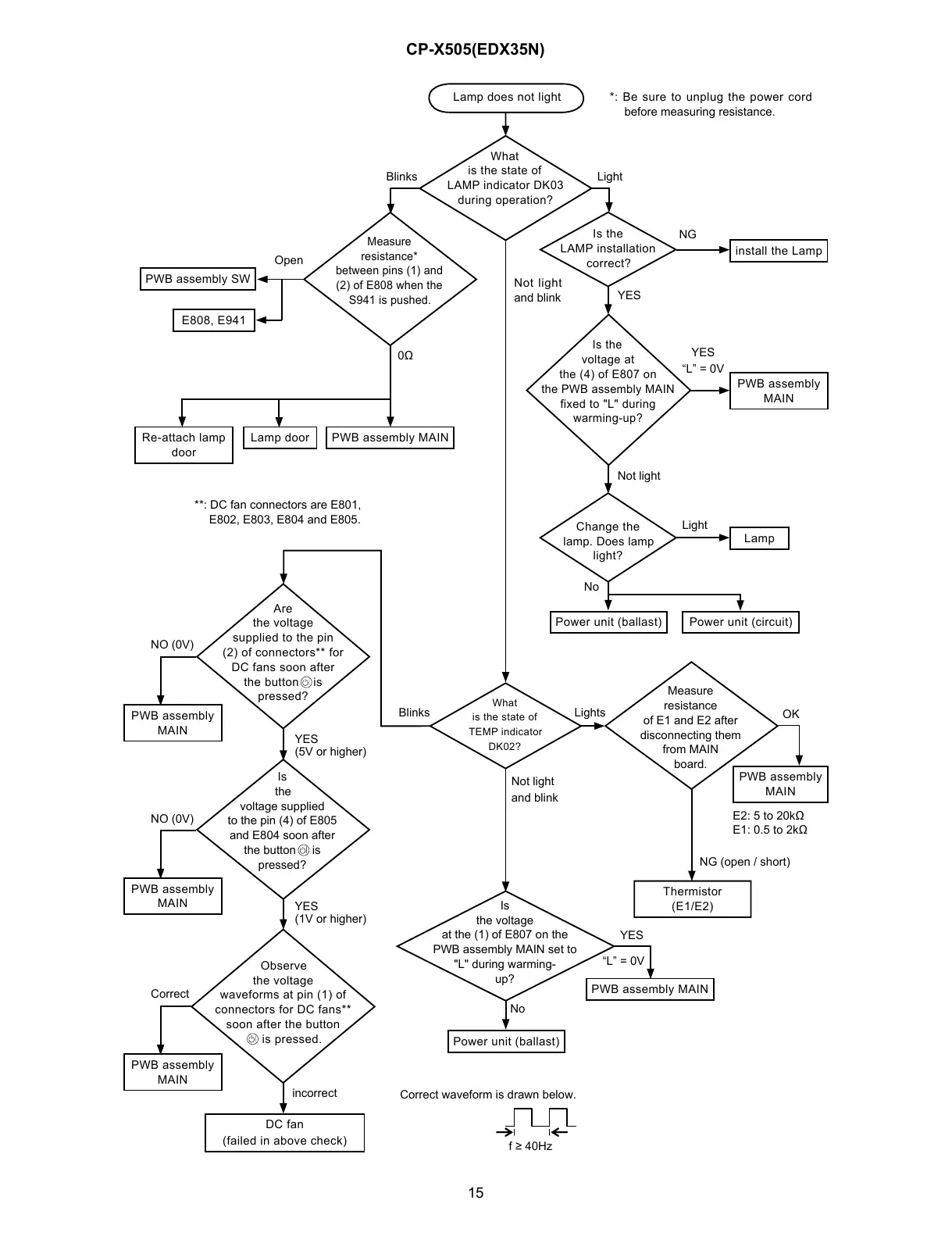
Lamp does not light
What
is the state of
LAMP indicator DK03
during operation?
Measure
resistance*
between pins (1) and
(2) of E808 when the
S941 is pushed.
PWB assembly SW
E808, E941
PWB assembly MAIN
Blinks
Open
0Ω
Is the
LAMP installation
correct?
Light
install the Lamp
PWB assembly
MAIN
Is the
voltage at
the (4) of E807 on
the PWB assembly MAIN
fixed to "L" during
warming-up?
NG
YES
“L” = 0V
Change the
lamp. Does lamp
light?
Lamp
Light
YES
Not light
Power unit (ballast) Power unit (circuit)
No
What
is the state of
TEMP indicator
DK02?
Thermistor
(E1/E2)
Is
the voltage
at the (1) of E807 on the
PWB assembly MAIN set to
"L" during warming-
up?
Not light
and blink
PWB assembly MAIN
YES
“L” = 0V
Power unit (ballast)
No
Are
the voltage
supplied to the pin
(2) of connectors** for
DC fans soon after
the button is
pressed?
Is
the
voltage supplied
to the pin (4) of E805
and E804 soon after
the button is
pressed?
Observe
the voltage
waveforms at pin (1) of
connectors for DC fans**
soon after the button
is pressed.
Blinks
DC fan
(failed in above check)
Correct waveform is drawn below.
f ≥ 40Hz
PWB assembly
MAIN
NO (0V)
PWB assembly
MAIN
NO (0V)
PWB assembly
MAIN
Correct
YES
YES
incorrect
*: Be sure to unplug the power cord
before measuring resistance.
Not light
and blink
**: DC fan connectors are E801,
E802, E803, E804 and E805.
(1V or higher)
(5V or higher)
Lamp door
Re-attach lamp
door
Lights
Measure
resistance
of E1 and E2 after
disconnecting them
from MAIN
board.
OK
PWB assembly
MAIN
E2: 5 to 20kΩ
E1: 0.5 to 2kΩ
NG (open / short)

 Loading...