-12-
• Electric Wiring
• Idle Adjust Screw
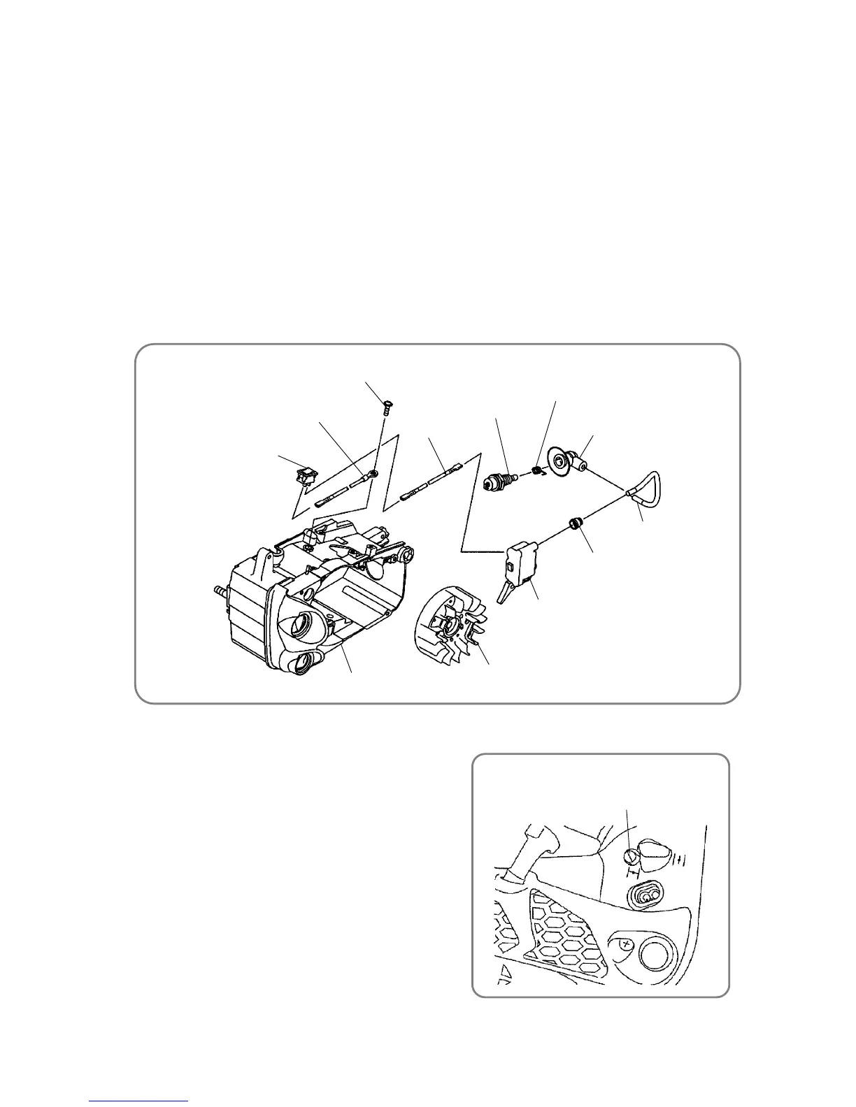
3. Electric Wiring
The following diagram shows the wiring.
(a) When connecting the High Voltage Cord [11] <11> and Spark Plug Cap Ass’y [10-1] <10-1>, insert the
High Voltage Cord [11] <11> with a small amount of oil applied to its tip into the Spark Plug Cap Ass’y
[10-1] <10-1> in the arrow direction, and then pull the cord from the rear of the Spark Plug Cap Ass’y
[10-1] <10-1>.
Then insert the Spark Plug Cap Ass’y [10-2] <10-2> into the High Voltage Cord [11] <11> so that the
assembly penetrates through the core wire of the high voltage cord.
Pull back the High Voltage Cord [11] <11> to the original position, and house the Spark Plug Cap Ass’y
[10-2] <10-2> within the Spark Plug Cap Ass’y [10-1] <10-1>.
(b) Use the Cord [220] <225> to connect the connector of the Ignition Coil Comp. [12] <12> to the Stop
Switch [181] <210>.
(c) After passing the Seal Lock Bolt M5 x 15 [88] <88> through the terminal of the Cord [221] <226>,
tighten the bolt onto the Engine Case Ass’y [123] <124>.
4. Adjusting the Carburetor
(a) Use the screw to adjust the carburetor.
• Idle Adjust Screw
Use the screw for adjusting the amount of air during idling.
Turning the screw clockwise increases the engine
revolutions; turning it counterclockwise decreases the
engine revolutions.
Idle Adjust Screw [224] <231>
Spark Plug [9] <9>
Spark Plug Cap Ass’y [10-2] <10-
Spark Plug Cap Ass’y [10-1] <10-
High Voltage Cord [11] <11>
Ignition Coil Comp. [12] <12>
Rubber Cap [13] <13>
Magneto Rotor Ass’y [29] <29>
Engine Case Ass’y [123] <124>
Stop Switch [181] <210>
Cord [221] <226>
Cord [220] <225>
Seal Lock Bolt M5u15 [88] <88>