-6-
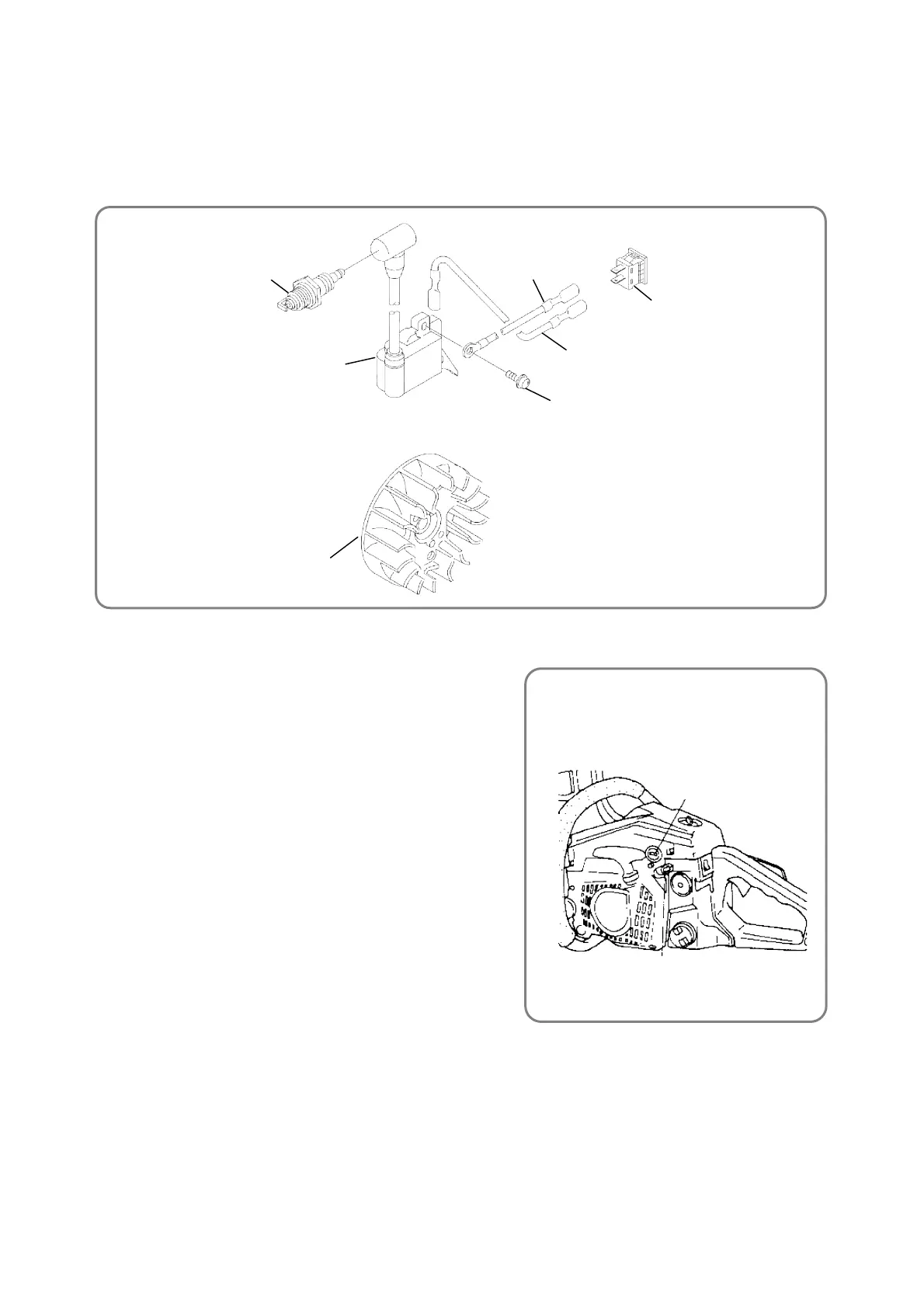
● Idle Adjusting Screw
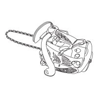
● Wiring diagram
Magneto Rotor Ass’y [67]
Stop Switch [91]
Hex. Socket Hd. Bolt (W/Flange) M4 x 18 [54]
Cord (A) [93]
Spark Plug [21]
Ignition Coil [53]
Cord (B) [55]
3. Wiring diagram
The following diagram shows the wiring.
(1) Use Cord (A) [93] to connect the connector of the Ignition Coil [53] to the Stop Switch [91].
(2) Connect Cord (B) [55] to the connector of the Stop Switch [91], and then tighten the Hex. Socket Hd.
Bolts M4 x 18 [54] to secure Cord (B) [55] to the Ignition Coil [53].
4. Adjustment of the carburetor ass’y
(1) Use the screw to adjust the Carburetor Ass’y [31].
• Idle Adjusting Screw [36]
Use the screw for adjusting the amount of air at idling.
Turning the screw clockwise increases the engine
revolutions; turning it counterclockwise decreases the
engine revolutions.
(2) Standard setting of the carburetor
• Idle Adjusting Screw [36]
2,900 to 3,300 min
-1
[rpm]
(Confirm that the saw chain does not rotate.)
(3) Fine adjustment
• Idling adjustment
(i) By using the Idle Adjusting Screw [36], set the
revolutions so that the saw chain does not start
rotating while the engine runs stably.
(ii) Set the idling revolutions to 2,900 to 3,300 min
-1
[rpm]
by using the Idle Adjusting Screw [36].
Idle Adjusting Screw [36]

 Loading...