-11-
Idle Adjust Screw [32]
• Idle Adjust Screw
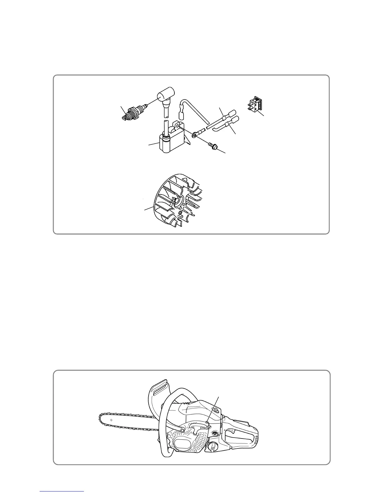
Magneto Sub Ass’y [80]
Stop Switch [93]
Hex. Socket Hd. Bolt (W/Flange)
M4 x 18 [51]
Cord (A) [47]
Spark Plug [13]
Ignition Coil [50]
Cord (B) [49]
3. Wiring diagram
The following diagram shows the wiring.
(1) Use Cord (A) [47] to connect the connector of the Ignition Coil [50] to the Stop Switch [93] .
(2) After connecting Cord (B) [49] to the connector of the Stop Switch [93], tighten the
Hex. Socket Hd. Bolt
(W/Flange) M4 x 18 [51]
inserted through the end of Cord (B) [49] into the Ignition Coil [50].
4. Adjustment of the Carburetor Ass’y
(1) Use the screw to adjust the Carburetor Ass’y [20]
• Idle Adjust Screw [32]
Use the screw for adjusting the amount of air during idling. Turning the screw clockwise increases
engine revolutions; turning it counterclockwise decreases engine revolutions.
(2) Standard setting of the carburetor
• Idle Adjust Screw [32]
2,900 to 3,300 min
-1
(rev./min)
(Confirm that the saw chain does not rotate.)
(3) Fine adjustment
• Idling adjustment
(a) By using the Idle Adjust Screw [32] , set revolutions so that the saw chain does not start rotating
while the engine runs stably.
(b) Set idling revolutions to 2,900 to 3,300 min
-1
(rev./min) by using the Idle Adjust Screw [32].
• Wiring diagram

 Loading...