--- 21 ---
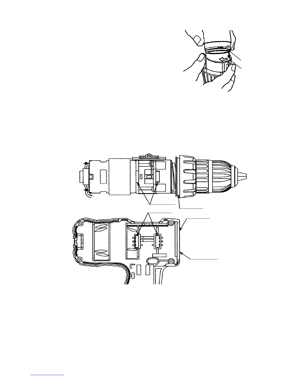
(f) Mount the assembly reassembled in step (1) and the assembly
reassembled in step (e) together. (See Fig. 12.)
Fit the projection of the Motor Spacer [24] <24> in the recess
of the Rear Case [14] <14> aligning the Shift Knob [35] <36>
with the positive side of the Motor [25] <25> and turn the
Motor Spacer [24] <24> clockwise when viewed from the rear
of the Motor [25] <25> until it can turn no further. During
installation, make sure that the pinion press-fitted onto the
shaft of the Motor [25] <25> and Planet Gear (A) Set [21]
<21> mesh properly.
Fig. 12
Projection
Recess
(4) Mounting the assembly reassembled in step (3) to Housing (A). (B) Set [29] <30>
(a) Mount the assembly reassembled in step (3) to Housing (A) [29] <30>. Note that the projections of the
Front Case [9] <9> and the Motor Spacer [24] <24> are engaged in the recesses of Housing (A) [29] <30>,
and the projection of Housing (A) [29] <30> is engaged in the groove of the Clutch Dial [4] <4>.
(See Fig. 13.)
(b) Mount the Pushing Button [33] <34> to Housing (A) [29] <30>. Check that the protrusion of the forward/
reverse changeover lever of the DC-Speed Control Switch [32] <33> is inserted into the groove of the
Pushing Button [33] <34>.
(c) Mount the Strap (Black) [39] <40> to Housing (A) [29] <30> .
(d) Set the assembly reassembled in step (c) to Housing (B) [29] <30> and secure it with the eight Tapping
Screws (W/Flange) D3 x 16 (Black) [26] <27>.
Fig. 13
Groove
Projection
Housing (A)
Recess
Projection
 Loading...