--- 20 ---
(i) Pay attention to the direction of the groove when mounting the Slide Ring Gear [17] <17> so that the
groove faces toward the Motor [25] <25>.
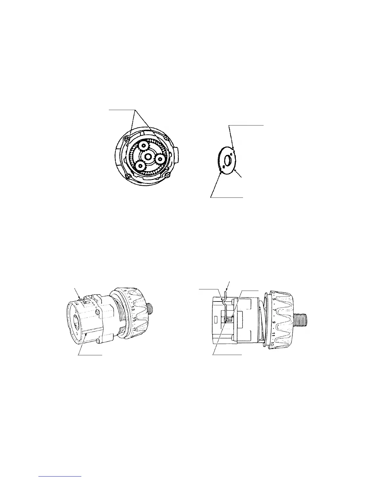
(ii) Mount the Front Case [9] <9> and the Rear Case [14] <14> together with the mark on the Front Case
[9] <9> aligned with the mark on the Rear Case [14] <14>. (See Fig. 11.)
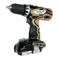
(iii) Fit Washer (B) [23] <23> in the Rear Case [14] <14> with the projections of Washer (B) [23] <23>
engaged with the recesses of the Rear Case [14] <14>, and turn Washer (B) [23] <23> clockwise until
it can turn no further. (See Fig. 10.)
Fig. 10
Recess
Projection
Projection
[23] <23>
Fig. 11
(c) Mount the Shift Arm [16] <16> to the assembly reassembled in step (b).
Facing the ridge of the Shift Arm [16] <16> toward the Motor [25] <25>, mount it to the unmarked side of
the assembly reassembled in step (b). Then fit the projections of the Shift Arm [16] <16> in the holes of the
Rear Case [14] <14> and make sure that the projections are fitted in the grooves of the Slide Ring Gear
[17] <17> mounted in the Rear Case [14] <14>. (See Fig. 11.)
(d) Mount the Drill Chuck [2] <2>.
Mount the Drill Chuck [2] <2> using the special repair tool (J-342, Code No. 324-582) and secure it with the
Special Screw (Left Hand) M6 x 23 [1] <1>.
(e) Mount the Shift Knob [35] <36> to the assembly reassembled in step (d).
When mounting the Shift Knob [35] <36> to the Shift Arm [16] <16>, make sure that the "LOW" mark on
the Shift Knob [35] <36> faces toward the Motor [25] <25> with the Shift Arm [16] <16> engaged with the
recess of the Shift Knob [35] <36>.
[16] <16>
[16] <16>
Ridge
Mark
Groove
Hole
 Loading...