--- 11 ---
(4) Disassembly of the gear unit
(a) Remove the Cap [4] from the Front Case [12]. Take care not to remove the Switch Plate [8] and the Nut
[9] from the Front Case [12] in this operation.
(b) Turn the Motor [31] counterclockwise when viewed from the rear and remove it from the Rear Case [20].
(c)
Remove the Shift Arm [22] from the Rear Case [20], and remove the Shift Knob [41] from the Shift Arm [22]
.
(d) Remove the Screw Set M3 x 12 (4 pcs.) [21] connecting the Front Case [12] and the Rear Case [20].
(e) Remove Washer (A) [19], Planet Gear (C) Set (3 pcs.) [18], Carrier [17], Ring Gear [16], Spacer Washer
[15], six Steel Balls D5 [14] and six Rollers [13] in sequence from the Front Case [12]. Take care not to
lose the six Steel Balls D5 [14] and the six Rollers [13] in this operation.
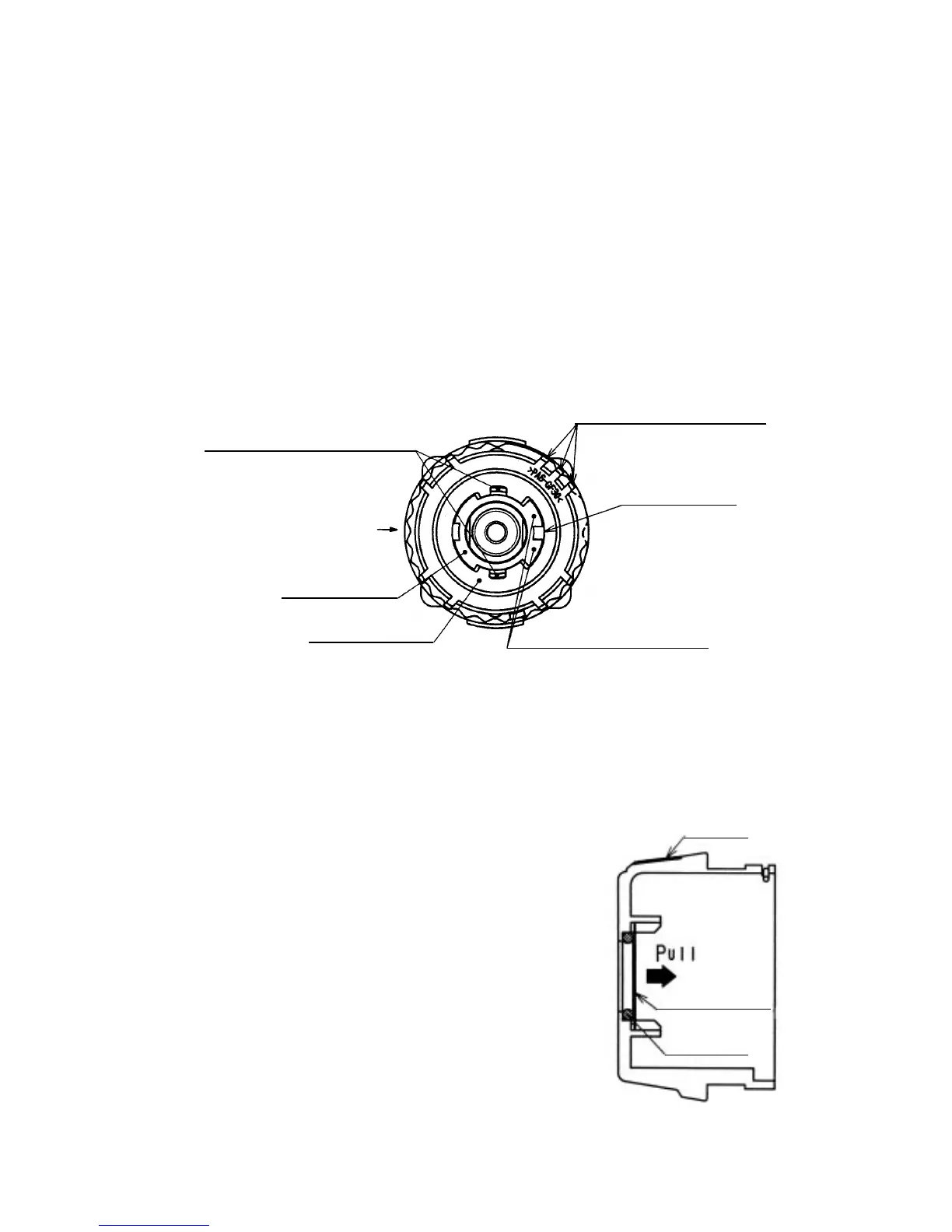
(5) Removal of the Switch Plate [8]
Turn the switch flange so as to fit the projection of the switch flange to the recess of the Switch Plate [8], then
remove the Switch Plate [8] from the Front Case [12]. (See Fig. 5.)
(7) Removal of the O-ring [6]
Pull out the Lock Washer [7] from the Cap [4] and remove the
O-ring [6]. (See Fig. 6.)
(8) Disassembly of the power supply unit
(Note) Do not remove the fin secured to the DC-speed Control
Switch [38] with a screw.
Remove the two Machine Screws (W/SP. Washer) M4 x 6 [34],
and take the Motor [31] and the Motor Spacer [30] apart.
Disconnect the Internal Wires (Black) [36] and (Red) [37] from
the Motor [31] with a soldering iron, then disconnect them from
the DC-speed Control Switch [38] with a soldering iron in the
same manner.
Fig. 5
Switch Plate [8]
Three projections of Nut [9]
Fig. 6
Lock Washer [7]
Cap [4]
O-ring [6]
Projection of switch frange
Marking of
Rear Case [20]
Recess of
Switch Plate [8]
Projections of Front Case [12]
Switch flange
(6) Removal of the Spring [10] and the Thrust Washer [11]
Turn the Nut [9] counterclockwise and remove it from the Front Case [12], then remove the Spring [10] and
Thrust Washer [11] from the Front Case [12].
(Note) Do not disassemble the Front Case [12].