English
— 11 —
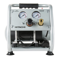
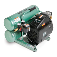
Knob of the pressure regulator
Joint
Outlet pressure
gauge
Fig. 11
The outlet pressure gauge indicates the air pressure
available at the outlet side of the regulator. This pressure
is controlled by the regulator and is always less or equal
to the air tank pressure. The air tank pressure gauge
indicates the reserve air pressure in the air tank(s).
When adjusting the pressure, check and make sure that
a pressure gauge for the tank has the pressure level
that is higher than that of the pressure to be adjusted. It
is also imperative that you make adjustment by slowly
starting up the pressure from the level that is lower than
the pressure to be adjusted.
WARNING: Check the manufacturer’s maximum
pressure rating for nailers, staplers
and accessories. Compressor outlet
pressure must be regulated so
as to never exceed the maximum
pressure rating of the nailers,
staplers and accessories.
CAUTION: Make sure the air fl ow to the regulator
is completely closed (pressure gauge
attached reads 0 PSI) before attaching
and disconnecting air hose.
3. Shutdown
A) To stop this compressor, move the engine switch
to the “Off ” position (Refer to the Engine Manual
accompanying this unit).
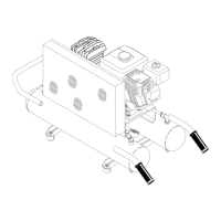
B) Gradually open the drain cock, take out the drainage
and all the compressed air inside the tank to prevent
any internal corrosion of the tank (Fig.12).
WARNING: Risk of bursting. When the tank
gets corroded, there is a risk of
breakdown. Water will condense
in the air tank. If not drained, water
will corrode and weaken the air tank
causing a risk of air tank rupture.
Drain tank daily or after 4 hours of
use. The drain contains moisture
in the air, abrasion particles, rust,
etc. To drain tank open valve
slowly and tilt compressor to empty
accumulated water.
Tank
Drain cock
open
open
close
close
Fig. 12
C) Allow the compressor to cool down.
D) Pull out the spark plug cap. Move the fuel valve
lever to the OFF position (refer to the Engine Manual
accompanying this unit).
E) Wipe this compressor clean and store in a safe,
nonfreezing area.
MAINTENANCE
WARNING: Turn off the engine switch. Remove
the compressed air from the air tank
before performing the maintenance
operations. Allow the compressor
to cool before performing the
maintenance operations. Always
stop engine and pull out the spark
plug cap to prevent any sudden
start of the engine.
Read the instruction manual before performing maintenance.
The following procedures must be performed when stopping
the compressor for maintenance or service.
A) Turn off the compressor.
B) Wait for this compressor to cool down before starting
service.
C) Open all drains.
D) Pull out the spark plug cap.
1. Cleaning the air intake fi lter
This fi lter is designed to clean air coming into the pump
(Fig. 13). To ensure the pump continually receives
clean, cool, dry air supply this fi lter must always be
clean and ventilation opening must always be free from
obstructions. Check this fi lter weekly.
WARNING: Never clean fi lter element with a
fl ammable liquid or solvent.
CAUTION: Do not operate without the air intake
fi lter.
000BookEC2610Elowes.indb11000BookEC2610Elowes.indb11 2018/03/0910:24:522018/03/0910:24:52