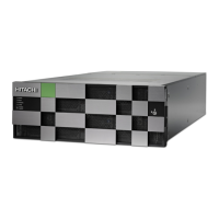
Table 15 Channel board box components
Model number Part description Quantity
DW-F800-CHBB PCP module 2
I/O expansion box (CHBB
chassis)
1
Power supply unit 2
PCIe switch board (fan x 5) 2
PCIe module 2
PCIe cable (1.5m) 2
Front bezel 1
Accessories kit 1
Table 16 Optional service processor
Model number Part description Quantity
HDW-F850-SVP.P Service processor
(Windo
ws 10 Enterprise)
1
Drive tray and drive configuration
The following table lists the supported maximum mountable drive trays and data drives
for the VSP G900 storage system.
Controller
chassis
Number of mountable
drive trays Maximum number of mountable drives
Drive trays Maximum SAS drive
Solid-state
drive
Flash
module
drive (FMD)
CBL DBS 48 1,152 1,152 N/A
DBL 48 576 N/A N/A
DBF 48 N/A N/A 576
DB60 24 1440 1,200 N/A
Drive tray and drive congur
ation
Appendix A: Storage system parts list
Hitachi Virtual Storage Platform G900 Hardware Reference Guide 61

 Loading...