EasyManua.ls Logo

Hitachi HA-3800 Service Manual

Hitachi HA-3800
20 pages
To Next Page IconTo Next Page
Page #1 background imageLoading...
Page #1 background image
No. 262EGF
HA-3SOO
CONTENTS
SPECTFICAT|ONS
.........1
FEATURES.
...........1
ADJUSTMENT....
.........3
DESCRIPTION
OF
THE
NEW
CIRCUITS.. .....4
CHECKING
OF
THE
OPERATION
OF
THE
PROTECTTON CrRCU rT ....
.........6
CIRCUIT DIAGRAM
......9
PRINTED WIRING BOARD
.........10
DISASSEM BLY AND REPLACEMENT.
.,.....12
REPLACEMENT PARTS
LIST
......14
FRONTAND REAR PANEL...
......17
SAFETY PRECAUTION
The
following
precautions
should be
observed when
servicing.
1.
Since many
parts
in
the
unit
have special
safety related
characteristics, always use
genuine
Hitachi's
replacement
parts.
Especially
critical
parts
in
the
power
circuit block should
not
be replaced
with other makers.
Critical
parts
are marked with
A
in
the
schematic
diagram
and circuit board diagram.
2. Before returning
a repaired unit
to the
customer,
the service technician must
thoroughly
test the
unit
to ascertain
that it is
completely
safe to
operate
without
danger
of
electrical
shock.
SPECIFICATIONS
Power
output
(Both
channels driven)
Power
bandwidth
Frequency
characteristics
TUNER, TAPE
PHONO
Harmonic
distortion
(8
ohmsl
(at
rated
output)
/.\
lat1l2
rated
outputl
I
ntermodulation distortion
latl/2
rated
output)
I
nput sensitivity/
lmpedance
PHONO
TUNER,
AUX
TAPE PLAY
'
Output level
TAPE REC
OUT
35 watts*
per
channel,
min. RMS
at
8
ohms
from 20 Hz
to
20
kHz,
with no
more
than 0.05% total hormonic
distortion.
35W/ch
+
35W/ch
(8
0hms, 1 kHz,
T.H.D.
0.05%)
35W/ch +
35W/ch
(4
ohms, 1 kHz,
T.H.D.0.05%)
10
Hz
-
30
kHz
(8
ohms,
l12Rated
T.H.D.0.1%)
20 Hz
-
70 kHz
(+0.5,
-3.0
dB)
RIAA
+
O.sdB
Less than 0.05%
Les
than 0.05%
Less than 0.05o/o
2.5 mY/47 k-ohms
'150
mV/40 k-ohms
150
mV/zl0
k-ohms
150 mV
Phono
overload level
Signal-to-noise
ratio
(lHF
A
PHONO
TUNER,
AUX, TAPE
Damping factor
Bass
control
Treble
control
Loudness
control
Subsonic filter
Power
supply
Power
consumption
Dimensions
Weight
200
mV
(at
1 kHz)
networkl
80 dB
100
dB
30
(1
kHz,
8
ohms)
+8
og
(1oo
Hz)
+8
da
(10
kHz)
+6
dB
(100
Hz)
+4
dB
(10
kHz)
20 Hz
AC 120
V 60 Hz,
-220
V filffi
Hz,
-240
V
50/60 Hz
or
-120
V
1220
V
I
240Y
filffi Hz
110 W
(at
1/10 rated
output)
180
W
(at
1/3
rated
output)
300 W
(at
rated
output)
zt35(W)
x83(H) x299(D)
mm
5.8 kg
FEATU RES
1.
Super linear
circuit
for low
switching
distor-
tion.
2. Equalizer
circuit with
high sens:tivity
and
S/N ratio.
3. 14 LEDs
power
indication.
Measured
pursuant
to the
Federal Trade Commission's
Trade Regulation
Rule
on
Power
Output
Claims for
amplifiers.
Electronic
protection
circuit.
Connection facilities
for
two
pairs
of
speakers.
Sleek and
chic design.
6.
SPECIFICATIONS
AND PARTS
ARE
SUBJECT TO
CHANGE
FOR IMPROVEMENT.
April
198
t
TOYOKAWA
WORKS
STEREO
AMPLIFIER
Question and Answer IconNeed help?

Do you have a question about the Hitachi HA-3800 and is the answer not in the manual?
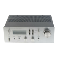
Hitachi HA-3800 Specifications

General IconGeneral
TypeStereo Integrated Amplifier
Output150mV (line)
Speaker Load Impedance4Ω to 16Ω
Input Sensitivity2.5mV (MM), 150mV (line)
Signal to Noise Ratio100dB (line)

Summary

Safety Precautions

Technical Specifications

Product Features

Adjustment Procedures

Idle Current Adjustment

Procedure to adjust the idle current for optimal performance.

Repair and Replacement Cautions

Important warnings for safe and correct component replacement during adjustments.

New Circuit Descriptions

Super Linear Circuit

Explanation of the 'Super linear' circuit for reduced switching distortion.

LED Power Meter Circuit

Details on the circuit driving the LED power level indicators.

Protection Circuit Operation Check

ASO Detection Circuit Check

Procedure to verify the ASO detection circuit's function for output transistors.

Protection Circuit Activation Issues

Describes common protection circuit activation issues and their solutions.

Circuit Diagram

Printed Wiring Board Layout

Block Diagram

Disassembly: Covers and Power Transistors

Removing External Components

Procedures for removing the unit's cover, escutcheon, and bottom plate.

Removing Power Transistors

Instructions for detaching the power transistors from the heatsink.

Safety Caution for Knob Operation

Warning regarding potential switch damage when pulling the knob.

Disassembly: Internal Boards and Components

Removing Printed Wiring Boards

Instructions for detaching the printed wiring boards and power transistors.

Replacement Parts List

Capacitors

List of replacement capacitors with part numbers, descriptions, and specifications.

Resistors

List of replacement resistors with part numbers, descriptions, and specifications.

Diodes, Thermistors, ICs, Transistors

List of replacement diodes, thermistors, ICs, and transistors with part numbers.

Variable Resistors, Coils, and Miscellaneous

List of replacement variable resistors, coils, fuses, switches, and other components.

Assembly and Dial Mechanism Parts

List of parts for final assembly, dial mechanism, and rear plate components.

Accessories

List of accessories such as socket adaptors and power supply cords.

Front and Rear Panel Controls

Related product manuals