EasyManua.ls Logo

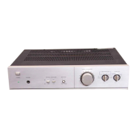
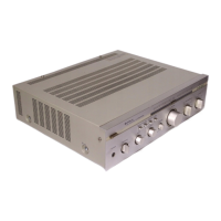
Hitachi HCA-7500 - Controls and Switches; Power Switch Operation; Power Indicator Light; Low Filter Function

Hitachi HCA-7500
11 pages
Print Icon
To Next Page IconTo Next Page
To Previous Page IconTo Previous Page
Loading...
Important
for
U.K.:
WARNING:
This
apparatus
must
be
earthed.
The
wires
in
this
mains
lead
are
coloured
in
accordance
with
the
following
code:
Green
and
Yellow
:
EARTH
Blue
:
NEUTRAL
Brown
:
LIVE
As
the
colours
of
the
wires
in
the
mains
lead
of
this
apparatus
may
not
correspond
with
the
coloured
markings
identifying
the
terminals
in
your
plug
proceed
as
follows.
The
wire
which
is
coloured
GREEN
and
YELLOW
must
be
connected
to
the
terminal
in
the
plug
which
is
marked
by
the
letter
E
or
by
the
safety
earth
symbol
+=
or
coloured
GREEN
or
GREEN
and
YELLOW.
The
wire
which
is
coloured
BLUE
must
be
connected
to
the
terminal
which
is
marked
with
the
letter
N
or
coloured
BLACK.
or
coloured
RED.
The
wire
which
is
coloured
BROWN
must
be
connected
to
the
terminal
which
is
marked
with
the
letter
L
CONTROLS
AND
SWITCHES
@
POWER
switch
When
this
switch
is
set
to
ON,
power
is
supplied
to
the
amplifier
and
the
POWER
INDICATOR
@
lights
up.
There
is
a
built-in
muting
circuit
so
that
the
relays
are
actuated
about
5
seconds
after
the
power
has
been
switched
on.
Then
the
amplifier
starts
normal
operation.
(2)
POWER
INDICATOR
This
lights
up
when
the
POWER
switch
(@®
is
set
to
ON.
(3)
LOW
FILTER
switch
When
this
switch
is
set
to
the
15
Hz
position,
low
frequency
noise
which
is
generated
by
warps
in
the
records
is
cut
out.
It
is
wise
to
keep
this
switch
at
the
15
Hz
position
since
it
is
effective
in
cutting
out
low
frequency
noise
outside
the
range
of
hearing
which
can
adversely
affect
the
speakers
(12
dB/oct.).
@
HIGH
FILTER
switch
Set
this
switch
to
the
8
kHz
position
when
you
want
to
cut
out
scratch
noise
from
records,
hiss
noise
from
tapes
and
high-frequency
noise
when
listening
to
a
broadcast.
This
switch
is
designed
to
cut
out
smoothly
the
treble
from
8
kHz
at
6
dB/oct.
©)
MODE
switch
This
switch allows
any
of
five
selections.
STEREO
REVERSE.
.
.This
reverses
the
left
and
right
channels.
NORMAL
..
.This
gives
a
normal
stereo
ef-
fect.
MONO
PR
Vee
oS
The
left
and
right
channel
signals
are
mixed.
RC
eee
Only
the
signals
from
the
left
input
terminals
are
repro-
duced
through
the
left
and
right
speakers.
Res
2
edd
oe
Only
the
signals
from
the
right
input
terminals
are
re-
produced
through
the
left
and
right
speakers.
©
BALANCE
control
Adjusts
the
balance
of
right
and
left
channel
levels.
@
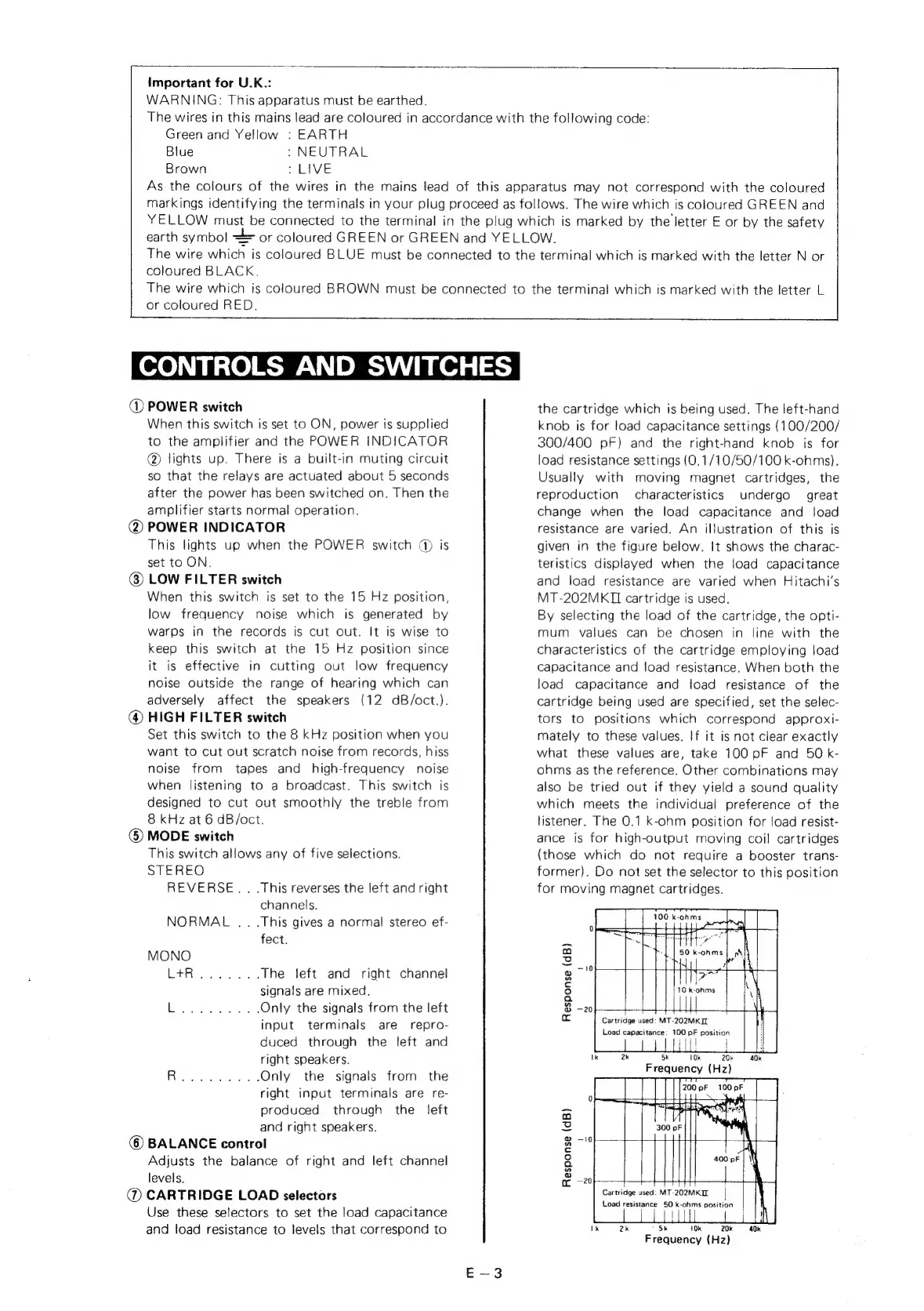
CARTRIDGE
LOAD
selectors
Use
these
selectors
to
set
the
load
capacitance
and
load
resistance
to
levels
that
correspond
to
the
cartridge
which
is
being
used.
The
left-hand
knob
is
for
load
capacitance
settings
(100/200/
300/400
pF)
and
the
right-hand
knob
is
for
load
resistance
settings
{(0.1/10/50/100
k-ohms).
Usually
with
moving
magnet
cartridges,
the
reproduction
characteristics
undergo
great
change
when
the
load
capacitance
and
load
resistance
are
varied.
An
illustration
of
this
is
given
in
the
figure
below.
It
shows
the
charac-
teristics
displayed
when
the
load
capacitance
and
load
resistance
are
varied
when
Hitachi's
MT-202MKIL
cartridge
is
used.
By
selecting
the
load
of
the
cartridge,
the
opti-
mum
values
can
be
chosen
in
line
with
the
characteristics
of
the
cartridge
employing
load
capacitance
and
load
resistance.
When
both
the
load
capacitance
and
load
resistance
of
the
cartridge
being
used
are
specified,
set
the
selec-
tors
to
positions
which
correspond
approxi-
mately
to
these
values.
If
it
is
not
clear
exactly
what
these
values
are,
take
100
pF
and
50
k-
ohms
as
the
reference.
Other
combinations
may
also
be
tried
out
if
they
yield
a
sound
quality
which
meets
the
individual
preference
of
the
listener.
The
0.1
k-ohm
position
for
load
resist-
ance
is
for
high-output
moving
coil
cartridges
(those
which
do
not
require
a
booster
trans-
former).
Do
not
set
the
selector
to
this
position
for
moving
magnet
cartridges.
Response
(dB)
+
-202MKIL
Load
capacitance:
100
pF
position
Cartridge
u:
Ik
2k
Sk
Sk
~~
0k
SCO
Frequency
(Hz)
Response
(dB)
Cartridge
used:
2
Load
resistance
50
k-ohms
position
Ik
2k
5k
10k
20k
40k
Frequency
(Hz)