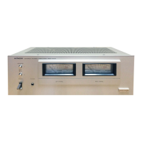
Do you have a question about the Hitachi HMA-7500 and is the answer not in the manual?
Steps to remove the main external parts of the unit for access.
Procedure for removing specific high-power components.
Guidance on handling and connecting audio board connectors.
Guidelines for correct installation of replacement parts.
Explanation of the function and use of the DC coupling switch.
Description of the role and importance of resistor R735.
Procedure for setting the quiescent current of the amplifier.
Procedure for setting the DC offset at the input stage.
Procedure for setting the DC offset at the output stage.
Steps for zero and sensitivity adjustment of the power meters.
Verifying the function of the ASO detection circuit for output transistors.
Verifying the operation of the speaker protection relay circuit.
Visual inspection of primary fuses, connectors, and parts.
Checking relay operation and signal output.
Procedure for setting the quiescent current of the amplifier.
Procedure for setting the DC voltage at the input.
Procedure for setting the DC voltage at the output.
Steps for zero and sensitivity adjustment of the meters.
Checking the operation of the ASO and speaker protection circuits.
Visual inspection of primary fuses, connectors, and parts.
Checking relay operation and signal output.
Procedure for testing POWER MOS FET transistors.