--- 30 ---
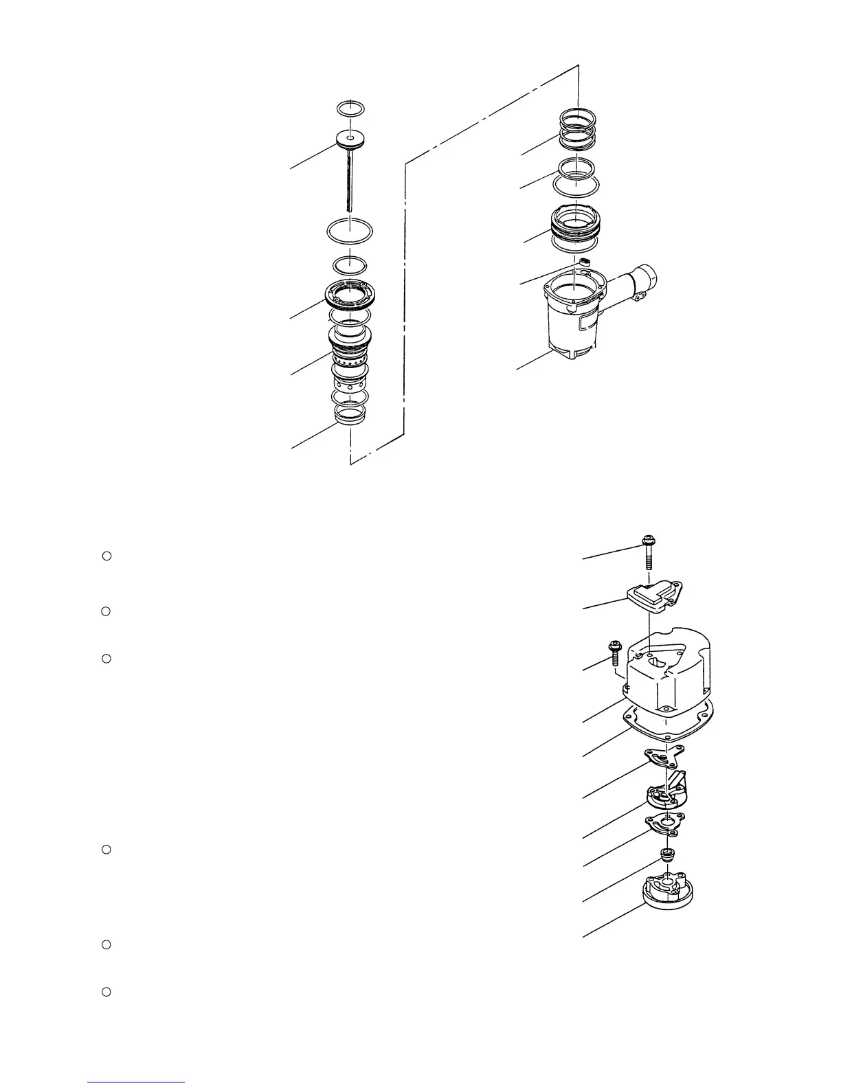
Fig. 10
Tool required:
Hexagonal bar wrench (5 mm)
Piston [12]
Cylinder Ring [19]
Cylinder [17]
Cylinder Guide [22]
Gasket (G) [23]
Body Ass'y [25]
Cylinder Plate [15]
Base Washer [21]
Cylinder Spring [20]
Hex. Socket Hd. Bolt
(W/Sp. Washer) M6 x 25 [3]
Top Cover [2]
Hex. Socket Hd. Bolt
(W/Flange) M6 x 45 [1]
Exhaust Cover [4]
(a) Disassembly
Remove the Exhaust Cover [4] as described in section
10-2-(1).
Loosen the three Hex. Socket Hd. Bolts (W/Flange)
M6 x 45 [1] and as illustrated in Fig. 11, remove the
Head Cap and Gasket Set [10], Exhaust Valve [9],
Exhaust Piece [7], Gasket (C) [8] and Gasket (F) [6].
(b) Reassembly
Reassembly can be accomplished by following the
disassembly procedures in reverse. However, special
attention should be given to the following items.
Be sure to check that the Exhaust Valve [9] is orange
and provided with a 1 mm dia. hole (Fig. 12) before
reassembly. Note that mounting a wrong exhaust valve
may cause a malfunction.
Gasket (C) [8] and Gasket (F) [6] should be replaced
with new genuine Hitachi parts.
Apply the designated grease to the outer circumference
of the Exhaust Valve [9] prior to reassembly.
Gasket (C) [8]
Exhaust Piece [7]
Gasket (F) [6]
Gasket (B) [5]
Exhaust Valve [9]
Head Cap and
Gasket Set [10]
(2) Head Cap and Gasket Set [10], Exhaust Piece [7] and related parts (See Fig. 11.)
Fig. 11 Disassembly of main body, upper part
 Loading...