--- 25 ---
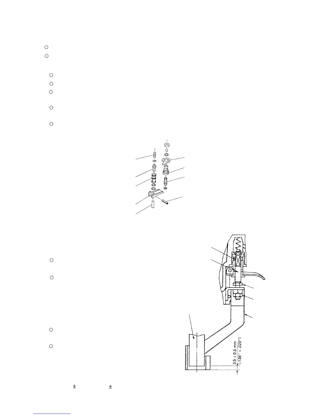
(a) Disassembly (See Fig. 16.)
Remove the Magazine [72] as described in section 10-2-(3).
Remove the Pushing Lever [46] as described in section 10-2-(3).
With the roll pin puller (3 mm (0.118") dia.), take out the Roll Pin D3 x 30 [43], and remove the Trigger [53],
Trigger Plunger [59] and Plunger (B) [54].
Insert the minus-hd. screwdriver into the groove of the Trigger Valve Bushing [58], and loosen it by turning it
to the left, being careful not to damage the groove.
After removing the Trigger Valve Bushing [58], pull down strongly on the Valve Bushing [51] to remove the
Valve Bushing [51], Plunger (A) [50] and the Plunger Spring [48].
10-3. Disassembly and Reassembly of the Control Valve Section
Tools required:
Roll pin puller (3 mm (0.118") dia.)
Minus-hd. screwdriver
Fig. 17
Fig. 17 Pushing lever adjustment
Trigger [53]
Plunger Spring [48]
Valve Bushing [51]
Plunger (A) [50]
Trigger Plunger [59]
Trigger Valve Bushing [58]
Valve Plate [57]
Roll Pin D3 x 30 [43]
Plunger (B) [54]
(b) Reassembly
Reassembly can be accomplished by following the
disassembly procedures in reverse. However, special
attention should be given to the following items.
Be very careful in handling the Plunger Spring [48],
as it can become twisted very easily.
To prevent the two O-rings on the outside of the Valve
Bushing [51] from being damaged when inserted into
the body, carefully apply grease to the body hole and
the outer circumference of the O-rings prior to
assembly.
(c) Adjustment of the Pushing Lever [46] (See Fig. 17.)
The Pushing Lever [46] can be adjusted by loosening
the Nut M5 [47] and turning the Safety Bolt [44].
Perform adjustment to a point where the resistance of
Plunger (B) [54] pushing up Plunger (A) [50] is felt
when the pushing lever is raised. At this point, the
lower end of the Nose [33] should be separated from
the lower end of the pushing lever by
3.5 mm 0.5 mm (.138" .020").
Fig. 16 Disassembly of valve
Plunger (A) [50]
Plunger (B) [54]
Nose [33]
Pushing Lever [46]
Nut M5 [47]
Safety Bolt [44]
 Loading...