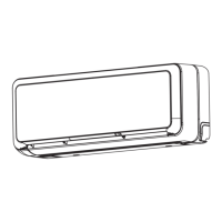
CONSTRUCTION AND DIMENSIONAL DIAGRAM
MODEL
φ65 Standard underfloor piping position
Cabinet
Front panel
Air outlet
Air inlet
Large dia. pipe
(φ9.52)
Small dia. pipe
(φ6.35)
55
Wireless remote
controller
Unit : mm
110
Piping hole
in right side
Piping hole
in left side
φ5 Hole for fixing to floor
φ9 Rear fixing hole for
anchor bolt
More than 150mm
More than
100mm
Drain hose
φ65 standard underfloor piping hole position
Cautions: 1. Use insulated pipes for both large and small diameters.
2. Use pipes of no more than 20m length.
3. Make sure the difference in heights between the indoor and outdoor units is 10m.
4. For built-in installation, make sure that the infrared receiver and indicator are not blocked.
5. Pipes can be laid out from the right, bottom or rear, when the unit is viewed from front.
6. Keep the clearance shown by for installation.
7. For built-in installation, keep the vertical deflector at top air outlet as flat as possible.
If it is inclined too much, heat will be trapped in the unit, which could cause faulty room temperature control.
8. An F-cable 1.6mm or 2.0mm dia. x 2 (control side) is used for the connection cable.
More than
100mm
More than
200mm
Less than 20mm
More than
150mm
More
150mm
More than 200mm
Built-in installation
Lattice door
760
681
45 52
40
61
19
469
130
80
600
130
80
45441
75.5
135
147
242
205
Infrared receiver
45
64
121
62
15
15
62
60
420170
115
92 29
60640
559
550
80
55
235
109
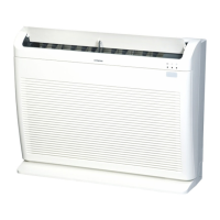
RAF-25RPA RAF-35RPA
INDOOR UNIT
27
 Loading...