Do you have a question about the Hitachi RAC-25WX8 and is the answer not in the manual?
| Brand | Hitachi |
|---|---|
| Model | RAC-25WX8 |
| Category | Air Conditioner |
| Language | English |
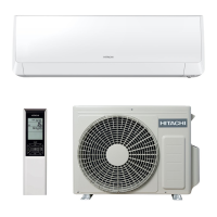
Overview of product models and key general specifications for HVAC units.
Essential safety instructions for technicians performing repairs on the unit.
Defines the scope and procedures for safe handling of semiconductor components.
Guidelines for safe handling of semiconductors, including grounding and static prevention.
Covers thunderstorm safety, power failure behavior, and operating temperature limits.
Detailed specifications for various components like fan motor, compressor, and transformer.
Critical safety guidelines to follow during the installation of the unit.
Safety measures for moving or maintaining the unit to prevent hazards.
Important safety rules to observe while the unit is in operation.
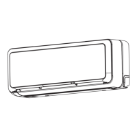
Identification and function of various components within the indoor unit.
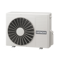
Identification and function of various components of the outdoor unit.
Explanation of indicator lamps and their meaning for unit status.
Description of the remote controller's buttons, functions, and operating range.
How the unit automatically selects heating or cooling based on room temperature.
Instructions for operating the unit in heating mode, including temperature and fan settings.
Guidance for using the dehumidifying function, including optimal temperature ranges.
Instructions for cooling operation, including temperature and fan speed settings.
Using the unit as an air circulator and for drying the indoor unit.
How to use the air purifying function for cleaner air.
Instructions for adjusting horizontal and vertical air deflectors for optimal airflow.
Step-by-step guide to setting the sleep timer for automatic unit shutdown.
Instructions for setting the ON-timer, OFF-timer, or ON/OFF-timer for automatic operation.
Procedure for safely replacing batteries in the remote controller.
Using the temporary switch when the remote controller is not working.
Recommendation to turn off the circuit breaker when not using the air conditioner.
Guidance on room conditions, filter care, heat sources, and long-term storage.
Crucial safety advice for operation, including lightning and electrical interference.
Step-by-step guide for installing the air cleansing filters correctly.
Detailed instructions for cleaning the air filters, including washing and drying.
Procedure for cleaning the electrical terminals of the dust collector.
Instructions for removing, cleaning, and reattaching the front panel.
Key checks for qualified service personnel to perform periodically.
Points to check before contacting service to diagnose operational issues.
Explanation of normal operational phenomena that may occur.
Detailed identification of indoor unit parts like air filters and panels.
Identification of outdoor unit parts including drain hose and earth terminal.
Explanation of indicator lamps (Filter, Operation, Timer) on the indoor unit.
Explanation of the auto restart feature after power interruptions.
How the unit automatically selects heating or cooling based on room temperature.
Instructions for operating the unit in heating mode, including temperature and fan settings.
Guidance for using the dehumidifying function, including optimal temperature ranges.
Instructions for cooling operation, including temperature and fan speed settings.
Tips for maintaining ideal room conditions and comfort for all users.
Guidance on air filter cleaning and effective use of timer functions.
Diagram showing the dimensions of the indoor unit in millimeters.
Diagram illustrating the dimensions and mounting details of the outdoor unit.
Specifications and operating modes for the thermostat component.
Details on fan motor specifications, power source, and wiring connections.
Specifications for the compressor, including model, phase, voltage, and resistance values.
Schematic showing the electrical connections within the indoor unit.
Schematic illustrating the electrical connections for the outdoor unit components.
Detailed schematic of the printed wiring board for the remote controller.
Diagram showing the functional blocks and signal flow within the indoor unit.
Diagram illustrating the functional blocks and signal flow within the outdoor unit.
Overview of basic operating modes (Fan, Cooling, Dehumidifying, Heating, Auto) and their functions.
Detailed explanation of operation logic for each mode based on temperature and time.
Table correlating fan speeds with different operation modes (Heating, Cooling, Dehumidifying).
Table showing how room temperature shifts affect fan speed settings.
Diagram illustrating compressor speed, fan operation, and indicators during cooling.
Table specifying temperature criteria for condensation engagement and release.
Explanation of sleep operation mode during cooling, including fan and compressor behavior.
Description of the defrost cycle during cooling operation.
Explanation of the defrost process using the reversing valve.
How to set the period during which defrosting is inhibited.
Schematic illustrating the refrigerant flow during cooling operation.
Schematic showing the refrigerant flow during heating operation.
Step-by-step guide for removing and reattaching the front panel.
Procedure for removing and reattaching the front cover, including filters.
Instructions for accessing and removing the control board assembly.
Procedure for removing and assembling the drain pan.
Steps for removing and reinstalling the fan motor and its components.
Final steps for attaching the front cover, including locking mechanisms.
Explanation of how the power circuit supplies voltage to the indoor unit and generates control voltages.
How the reset circuit initializes the microcomputer upon power-on or failure recovery.
Waveform analysis of the reset circuit's voltage behavior during power transitions.
Circuit diagram and voltage characteristics for the room temperature sensor.
Circuit diagram and voltage characteristics for the heat exchanger temperature sensor.
Explanation of the PWM pulse control for the fan motor and feedback mechanism.
Waveforms illustrating fan motor control signals and rotation feedback.
How the buzzer circuit generates sound signals using a square wave and piezoelectric element.
How the light receiving unit processes infrared signals from the remote control.
How the microcomputer reads data from E²PROM for initial settings and self-diagnosis.
Explanation of the temporary switch circuit for operating the unit without a remote.
Description of the two P.W.B.s (Power and Main) and harmonics improvement circuit.
Explanation of AC to DC conversion, harmonic limit, and voltage variations.
Details on the rectifier (DB2) and current shaping components (DB3, L1, C023, L2).
Explanation of circuits for voltage smoothing (C021, C022) and rectification (DB1, C41).
Circuits for absorbing noise (C001-C003, C011, L101, L102) and surge protection (SA1, VS1-VS3).
Role of resistors R002 and R007 in protecting against rush current during startup.
Signal transmission from outdoor to indoor microcomputer via DC 35V line.
Signal transmission from indoor to outdoor microcomputer via DC 35V line.
Diagram illustrating the interface circuit for communication between indoor and outdoor microcomputers.
Voltage waveforms showing communication signals from outdoor to indoor microcomputers.
Voltage waveforms illustrating communication signals from indoor to outdoor microcomputers.
Format for serial communication between outdoor and indoor microcomputers.
Exploded view diagram of the indoor unit with numbered parts.
List of indoor unit parts with part numbers, quantity, and designation.
List of indoor unit parts, including remote control and screw caps.
Exploded view diagram of the outdoor unit with numbered parts.
Comprehensive list of outdoor unit parts with part numbers and designations.