NO. 0083E
SPECIFICATIONS AND PARTS ARE SUBJECT TO CHANGE FOR IMPROVEMENT
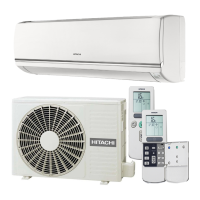
ROOM AIR CONDITIONER
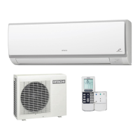
INDOOR UNIT + OUTDOOR UNIT
Hitachi Household Appliances(Wuhu) Co.,Ltd.
SERVICE MANUAL
REFER TO THE FOUNDATION MANUAL
TECHNICAL INFORMATION
FOR SERVICE PERSONNEL ONLY
(W)
(A)
(kW)
(B.T.U./h)
(W)
(A)
(kW)
(B.T.U./h)
W
H
D
(kg)
RAS-10PH1 RAC-10PH1
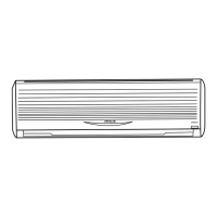
DC INVERTER (WALL TYPE)
TYPE
MODEL
POWER SOURCE
TOTAL INPUT
TOTAL AMPERES
CAPACITY
TOTAL INPUT
TOTAL AMPERES
CAPACITY
DIMENSIONS
(mm)
NET WEIGHT
SPECIFICATIONS
780
280
218
CONTENTS
SPECIFICATIONS ------------------------------------------------------------------- 6
HOW TO USE ----------------------------------------------------------------------- 7
CONSTRUCTION AND DIMENSIONAL DIAGRAM --------------------- 19
MAIN PARTS COMPONENT --------------------------------------------------- 20
WIRING DIAGRAM ---------------------------------------------------------------- 22
CIRCUIT DIAGRAM --------------------------------------------------------------- 23
RAS- RAC-10
RAS- RAC-14
COOLING
HEATING
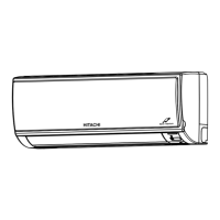
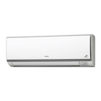
INDOOR UNIT
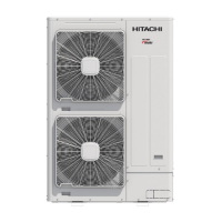
OUTDOOR UNIT
INDOOR UNIT
OUTDOOR UNIT
RAS-08PH1 RAC-08PH1
INDOOR UNIT
OUTDOOR UNIT
1 PHASE, 50 Hz, 220-230V1 PHASE, 50 Hz, 220-230V
2.50 (0.90 ~ 3.10)
15,01 )0
505
27
780
280
218
548
1 PHASE, 50 Hz, 220-230V
13,65 )0
13,648 (3,070 ~ 17,060)
After installation
RAS-14PH1 RAC-14PH1
BLOCK DIAGRAM ----------------------------------------------------------------- 26
BASIC MODE ----------------------------------------------------------------------- 27
REFRIGERATING CYCLE DIAGRAM --------------------------------------- 36
--------------------------------------
DESCRIPTION OF MAIN CIRCUIT OPERATION ----------------------- 37
SERVICE CALL Q & A ---------------------------------------------------------- 79
TROUBLE SHOOTING ----------------------------------------------------------- 82
Procedure for Disassembly and Reassembly 105
PARTS LIST AND DIAGRAM --------------------------------------------------
700 (+68) 750 (+91)
258 (+48) 288 (+47)
HHAW
700 (155 ~ 1,290)
8,530 (3,070 ~ 10,580)
3.40 (0.90 ~ 4.40)
11,600 (3,070 ~
7.5
780
280
218
2.00 (0.90 ~ 2.50)
10,92 )0
505
27
700 (+68)
258 (+48)
580 (155 ~ 1,010)
3.10-2.97
6,820 (3,070 ~ 8,530)
620 (115 ~ 970)
3.32-3.17
2.50 (0.90 ~ 3.20)
8,530 (3,070 ~
7.5
1090 (155 ~ 1,460)
5.22-4.99
3.50 (0.90 ~ 4.00)
11,940 (3,070 ~
1,100 (115 ~ 1,440)
5.26-5.03
4.20 (0.90 ~ 5.00)
7.5 36
10PH
RAS- RAC-08
08PH
14PH
INDOOR UNIT
RAS-08PH1
RAS-10PH1
RAS-14PH1
OUTDOOR UNIT
RAC-08PH1
RAC-10PH1
RAC-14PH1
3.75-3.59
880 (115 ~ 1250)
4.71-4.51
1
1
1
PH1
PH1
PH1
108
1