EasyManua.ls Logo

Hitachi RAS-18FH6 User Manual

Hitachi RAS-18FH6
96 pages
To Next Page IconTo Next Page
Page #1 background imageLoading...
Page #1 background image
NO. 0024E
SPECIFICATIONS AND PARTS ARE SUBJECT TO CHANGE FOR IMPROVEMENT
ROOM AIR CONDITIONER
INDOOR UNIT + OUTDOOR UNIT
FEBRUARY 2008 Hitachi Household Appliances(Wuhu) Co.,Ltd.
SERVICE MANUAL
AW
REFER TO THE FOUNDATION MANUAL
TECHNICAL INFORMATION
FOR SERVICE PERSONNEL ONLY
(W)
(A)
(kW)
(B.T.U./h)
(W)
(A)
(kW)
(B.T.U./h)
W
H
D
(kg)
RAS-18FH6 RAC-18YH6
DC INVERTER (WALL TYPE)
TYPE
MODEL
POWER SOURCE
TOTAL INPUT
TOTAL AMPERES
CAPACITY
TOTAL INPUT
TOTAL AMPERES
CAPACITY
DIMENSIONS
(mm)
NET WEIGHT
SPECIFICATIONS
780
280
220
9.5
RAS-18FH6
RAS-25FH6
CONTENTS
SPECIFICATIONS ------------------------------------------------------------------- 4
HOW TO USE ----------------------------------------------------------------------- 5
CONSTRUCTION AND DIMENSIONAL DIAGRAM --------------------- 15
MAIN PARTS COMPONENT --------------------------------------------------- 17
WIRING DIAGRAM ---------------------------------------------------------------- 19
CIRCUIT DIAGRAM --------------------------------------------------------------- 20
RAS-18FH6
RAC-18YH6
RAS-25FH6
RAC-25YH6
RAC-18YH6
RAC-25YH6
COOLING
HEATING
INDOOR UNIT
OUTDOOR UNIT
INDOOR UNIT
OUTDOOR UNIT
1 PHASE, 50 Hz, 220-230V
550 (155 ~ 1,010)
2.95-2.81
2.00 (0.90 ~ 2.50)
6,820 (3,070 ~ 8,530)
580 (115 ~ 970)
2.93-2.81
2.50 (0.90 ~ 3.20)
8,530 (3,070 ~ 10,920)
505
27
780
280
220
9.5
505
27
1 PHASE, 50 Hz, 220-230V
700 (155 ~ 1,290)
3.75-3.59
2.50 (0.90 ~ 3.10)
8,530 (3,070 ~ 10,580)
880 (115 ~ 1,250)
4.45-4.26
3.40 (0.90 ~ 4.40)
11,600 (3,070 ~ 15,010)
After installation
RAS-25FH6 RAC-25YH6
BLOCK DIAGRAM ----------------------------------------------------------------- 22
BASIC MODE ----------------------------------------------------------------------- 23
REFRIGERATING CYCLE DIAGRAM --------------------------------------
--------------------------------------
- 29
DESCRIPTION OF MAIN CIRCUIT OPERATION ----------------------- 30
SERVICE CALL Q & A ---------------------------------------------------------- 60
TROUBLE SHOOTING ----------------------------------------------------------- 63
Procedure for Disassembly and Reassembly 88
PARTS LIST AND DIAGRAM -------------------------------------------------- 90
700 (+68) 700 (+68)
258 (+48) 258 (+48)
RAS_AW_000covere 2008.03.07, 18:051

Table of Contents

Question and Answer IconNeed help?

Do you have a question about the Hitachi RAS-18FH6 and is the answer not in the manual?

Hitachi RAS-18FH6 Specifications

General IconGeneral
BrandHitachi
ModelRAS-18FH6
CategoryAir Conditioner
LanguageEnglish

Summary

SPECIFICATIONS

SAFETY DURING REPAIR WORK

WORKING STANDARDS FOR PREVENTING BREAKAGE OF SEMICONDUCTORS

Items to be observed in handling

Guidelines for safe handling and storage of semiconductor components to prevent damage.

CAUTION

HOW TO USE

SAFETY PRECAUTION

General safety precautions for using the air conditioner unit correctly and safely.

PRECAUTIONS DURING INSTALLATION

Guidelines and warnings for the safe and proper installation of the air conditioner.

PRECAUTIONS DURING OPERATION

Safety measures and warnings to be followed during the normal operation of the unit.

PRECAUTIONS DURING SHIFTING OR MAINTENANCE

Safety advice for moving, maintaining, or servicing the air conditioner unit.

NAMES AND FUNCTIONS OF EACH PART

INDOOR UNIT

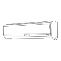
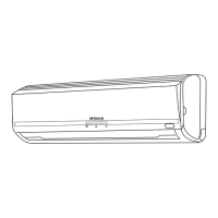
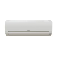
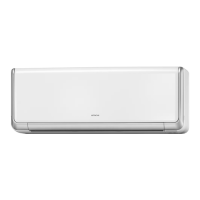
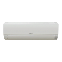
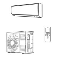
Identification and description of the various components of the indoor unit.

OUTDOOR UNIT

Identification and description of the various components of the outdoor unit.

INDOOR UNIT INDICATIONS

Explanation of the indicator lights on the indoor unit and their meanings.

NAMES AND FUNCTIONS OF EACH PART

REMOTE CONTROLLER

Detailed explanation of the remote control's buttons and functions for operating the unit.

VARIOUS FUNCTIONS

Auto Restart Control

Explanation of the automatic restart feature after a power interruption.

AUTOMATIC OPERATION

How the unit automatically selects the optimal cooling or heating mode based on temperature.

HEATING OPERATION

DEHUMIDIFYING OPERATION

COOLING OPERATION

FAN OPERATION

HOW TO SET THE TIMER

HOW TO SET THE SLEEP TIMER

HOW TO EXCHANGE THE BATTERIES IN THE REMOTE CONTROLLER

MAINTENANCE

AIR FILTER

Instructions for cleaning or replacing the air filter to maintain performance.

CLEANING OF FRONT PANEL

Guide on how to clean the front panel of the indoor unit.

MAINTENANCE AT BEGINNING OF LONG OFF PERIOD

Procedure for preparing the unit for extended periods of non-operation.

INFORMATION

CAPABILITIES

Information on the heating performance of the unit under various conditions.

REGULAR INSPECTION

Periodic checks to ensure the unit's safety and proper functioning.

AFTER SALES SERVICE AND WARRANTY

Information regarding service inquiries and warranty details.

VARIOUS FUNCTIONS

Overview of additional functions available on the unit.

TIMER PROGRAMMING/SLEEP TIMER OPERATION

How to program and use the timer and sleep timer features.

CONSTRUCTION AND DIMENSIONAL DIAGRAM

INDOOR UNIT

Diagrams showing the physical structure and dimensions of the indoor unit.

CONSTRUCTION AND DIMENSIONAL DIAGRAM

OUTDOOR UNIT

Diagrams illustrating the physical structure and dimensions of the outdoor unit.

MAIN PARTS COMPONENT

THERMOSTAT

Specifications and details related to the thermostat component.

FAN MOTOR

Specifications and connection details for the fan motor.

MAIN ELECTRIC COMPONENTS FOR OUTDOOR UNIT

List and ratings of key electrical components used in the outdoor unit.

COMPRESSOR MOTOR

WIRING DIAGRAM

CIRCUIT DIAGRAM

BLOCK DIAGRAM

BASIC MODE

REFRIGERATING CYCLE DIAGRAM

DESCRIPTION OF MAIN CIRCUIT OPERATION

1. Reset Circuit

Explanation of the circuit responsible for initializing the microcomputer.

DESCRIPTION OF MAIN CIRCUIT OPERATION

2. Receiver Circuit

Description of the circuit that receives signals from the remote controller.

3. Buzzer Circuit

Explanation of the circuit that generates audible beeps for operation feedback.

DESCRIPTION OF MAIN CIRCUIT OPERATION

4. Auto Sweep Motor Circuit

Details of the circuit controlling the automatic air deflector movement.

DESCRIPTION OF MAIN CIRCUIT OPERATION

5. Initial Setting Circuit (IC401)

Explanation of the circuit that sets initial operational parameters upon power-up.

6. Power Supply

Overview of the power supply circuits that provide voltage to various components.

DESCRIPTION OF MAIN CIRCUIT OPERATION

7. Fan Motor Drive Circuit

Explanation of the circuit that controls the indoor fan motor speed.

DESCRIPTION OF MAIN CIRCUIT OPERATION

1. Power circuit

Detailed explanation of the main power conversion circuit for the unit.

DESCRIPTION OF MAIN CIRCUIT OPERATION

2. Indoor/Outdoor Interface Circuit

Description of the communication interface between indoor and outdoor units.

DESCRIPTION OF MAIN CIRCUIT OPERATION

3. Intelligent power module circuit (IPM circuit)

Explanation of the IPM circuit that drives the compressor motor.

DESCRIPTION OF MAIN CIRCUIT OPERATION

5. Power Circuit for P.W.B.

Detailed explanation of the power circuit on the Printed Wiring Board (PWB).

DESCRIPTION OF MAIN CIRCUIT OPERATION

6. Peripheral circuits of microcomputer

Details on circuits connected to the microcomputer for its operation.

6-1. Peak current cutoff circuit

Explanation of the circuit that protects against excessive current.

DESCRIPTION OF MAIN CIRCUIT OPERATION

6-2. Overload control circuit (OVL control circuit)

Description of the circuit that prevents compressor overload.

DESCRIPTION OF MAIN CIRCUIT OPERATION

6-3. Reset Circuit

Explanation of the circuit that resets the microcomputer.

DESCRIPTION OF MAIN CIRCUIT OPERATION

6-4. Temperature Detection Circuit

Explanation of circuits that detect temperatures for operation control.

DESCRIPTION OF MAIN CIRCUIT OPERATION

6-5. Reversing valve control circuit

Explanation of the circuit that controls the refrigerant reversing valve.

DESCRIPTION OF MAIN CIRCUIT OPERATION

6-6. Electric expansion valve control circuit

Explanation of the circuit controlling the electric expansion valve.

DESCRIPTION OF MAIN CIRCUIT OPERATION

6-7. Outdoor DC Fan Motor control circuit

Explanation of the circuit that controls the outdoor DC fan motor.

SERVICE CALL Q & A

COOLING MODE

Questions and answers related to issues encountered during cooling operation.

DEHUMIDIFYING MODE

Questions and answers addressing problems during dehumidifying operation.

HEATING MODE

Questions and answers for troubleshooting heating operation issues.

SERVICE CALL Q & A

OTHERS

Questions and answers for various other operational issues and phenomena.

TROUBLE SHOOTING

PRECAUTIONS FOR CHECKING

Essential precautions to take before and during troubleshooting procedures.

DISCHARGE, PROCEDURE AND POWER SHUT OFF METHOD FOR POWER CIRCUIT

STRUCTURE OF AN INDOOR UNIT ELECTRIC PARTS

Removing electrical parts

Steps for safely removing electrical components from the indoor unit.

Removing control P.W.B.

Procedure for removing the control Printed Wiring Board (PWB).

Removing the indicating P.W.B.

Procedure for removing the indicating Printed Wiring Board (PWB).

Other Cautions

Cautions concerning ICP (IC Protector)

Specific warnings and precautions related to the IC protector.

THE SUPPORT FUNCTION OF FAILURE DIAGNOSIS

TROUBLESHOOTING WHEN TIMER LAMP BLINKS.

SELF-DIAGNOSIS LIGHTING MODE

OUTDOOR UNIT

CHECKING THE INDOOR/OUTDOOR UNIT ELECTRICAL PARTS AND REFRIGERATING

CHECKING THE INDOOR UNIT ELECTRICAL PARTS

1. Power does not come on (no operation)

Troubleshooting steps when the unit fails to power on or operate.

CHECKING THE INDOOR UNIT ELECTRICAL PARTS

2. Indoor fan does not operate (others are normal)

Troubleshooting steps if the indoor fan fails to operate while other functions are normal.

3. Air deflector does not move (others are normal)

Troubleshooting steps if the air deflector fails to move while other functions are normal.

CHECKING THE INDOOR UNIT ELECTRICAL PARTS

4. Check the control P.W.B. (power circuit)

Procedures for checking the power circuit on the control Printed Wiring Board (PWB).

CHECKING THE REMOTE CONTROLLER

CHECKING OUTDOOR UNIT ELECTRICAL PARTS

HOW TO CHANGE THE SHIFT VALUE FOR SETTING TEMPERATURE

PROCEDURE

Steps for adjusting temperature settings via the remote controller's shift value.

CHECKING THE REFRIGERATING CYCLE (JUDGING BETWEEN GAS LEAKAGE AND COMPRESSOR DEFECTIVE)

1. Troubleshooting procedure (No operation, No heating, No cooling)

Diagnostic steps for issues related to gas leakage or compressor defects.

HOW TO OPERATE USING THE SERVICE SWITCH THE OUTDOOR UNIT

HOW TO OPERATE THE OUTDOOR UNIT INDEPENDENTLY

IPM (Intelligent Power Module) DIAGNOSIS

Procedure for Disassembly and Reassembly

INDOOR UNIT RAS-18FH6, RAS-25FH6

Steps for disassembling and reassembling the indoor unit components.

Procedure for Disassembly and Reassembly

4. Tangential air flow fan and fan motor

Steps for removing the tangential fan and fan motor assembly.

<OUTDOOR UNIT> MODEL RAC-18YH6, RAC-25YH6

1. Electrical Parts

Instructions for removing and accessing the electrical parts of the outdoor unit.

PARTS LIST AND DIAGRAM

INDOOR UNIT MODEL: RAS-18FH6, RAS-25FH6

Illustrated list of all replaceable parts for the indoor unit.

PARTS LIST AND DIAGRAM

OUTDOOR UNIT MODEL: RAC-18YH6, RAC-25YH6

Illustrated list of all replaceable parts for the outdoor unit.

Related product manuals