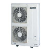
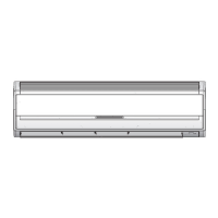
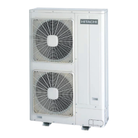
Do you have a question about the Hitachi RAS-8FSG and is the answer not in the manual?
Lists various types of indoor units like In-the-Ceiling, Cassette, Wall, Floor, and their capacities.
Lists FSG(1), FS3, FS5, FXG, FX3 series outdoor units with their model numbers.
Lists Total Heat Exchangers with their model numbers.
Covers basic checks like switch settings, wiring, and 7-segment display for initial troubleshooting.
Explains settings for indoor and outdoor units' dip switches and rotary switches for proper operation.
Details how to check electrical wiring connections, cable specifications, and grounding.
Describes simple checks using the outdoor unit's 7-segment LED display for diagnostics.
Provides steps for emergency operation when the inverter compressor fails.
Addresses issues related to no lights, LCD indication, or unit operation due to power failure.
Troubleshoots 'RUN' lamp flickering and communication issues between units.
Covers system malfunctions like no operation or compressor issues without specific alarm codes.
Guides through systematic troubleshooting steps, often by using alarm codes.
Lists various alarm codes, their contents, and leading causes for quick reference.
Provides detailed procedures for troubleshooting based on specific alarm codes indicated by the system.
Explains how to use the remote control switch's check mode for diagnostic purposes.
Details how to check operation conditions and abnormalities using the outdoor unit's 7-segment display.
Explains the function and settings of rotary switches, dip switches, and LEDs on the PCBs.
Outlines procedures for checking major components of the HVAC system.
Details the self-checking procedure for Printed Circuit Boards using the remote control switch.
Explains how to perform self-checking of the remote control switch itself to verify its functionality.
Describes self-checking procedures for indoor unit PCBs, excluding specific models.
Provides steps for self-checking the 7-Day Timer and its LCD display functionality.
Explains the self-checking procedure for the Central Station unit's functions.
Covers essential checks like high voltage discharge and specific component testing.
Guides on performing test runs to verify system operation after installation or repair.
Details the procedure for initiating a test run using the remote control switch.
Explains how to perform a test run using the outdoor unit's dip switches.
Provides a checklist for test operation and refrigerant cycle checks for specific series.
Covers servicing procedures for the outdoor unit components like fans, compressors, and sensors.
Instructions for removing the air intake grille from the outdoor unit.
Steps for removing the front service panel to access internal components.
Guide on how to remove the fan guard nets from the outdoor unit.
Detailed instructions for removing the outdoor fan assembly.
Procedure for safely removing the compressor for specific models.
Steps for removing compressors for a range of models.
Specific instructions for removing compressors in MC1 and MC2 configurations.
Specific instructions for removing compressors in MC3 and MC4 configurations.
Detailed guide for removing pressure-related components.
Procedure for removing the coil from the reversing valve.
Steps for removing solenoid valve coils for various models.
Instructions for removing thermistors attached to the liquid pipe.
Detailed procedure for removing the reversing valve for specific models.
Specific procedure for removing the reversing valve for high-capacity models.
Instructions for removing various electrical components from the outdoor unit.
Instructions for removing electrical components from high-capacity outdoor units.
Servicing procedures for specific RPI models in the In-the-Ceiling type.
Steps to remove the long-life filter from the In-the-Ceiling unit.
Guide for safely removing the PCB from the In-the-Ceiling unit.
Detailed process for removing the fan and motor assembly from In-the-Ceiling units.
Instructions for removing thermistors from liquid and gas pipes.
Steps for removing the electronic expansion valve coil.
Procedure for safely removing the float switch.
Guide for removing the drain pump from specific In-the-Ceiling units.
Instructions for removing the drain pan from In-the-Ceiling units.
Servicing procedures for higher capacity RPI models.
Steps to remove the long-life filter for RPI-8/10FSG1.
Guide for removing the PCB from RPI-8/10FSG1 units.
Process for removing the fan and motor assembly from RPI-8/10FSG1.
Instructions for removing the expansion valve and thermistors.
Servicing procedures specific to the 4-Way Cassette indoor unit type.
Steps to remove the long-life filter from the 4-Way Cassette unit.
Guide for removing the air intake grille of the 4-Way Cassette unit.
Instructions for accessing the electrical box by removing its cover.
Steps to remove the optional air panel for accessory installation.
Detailed process for removing the fan runner and motor assembly.
Instructions for removing the bell-mouth component.
Guide for safely removing the PCB.
Steps for removing the drain pan assembly.
Procedure for removing the drain-up mechanism.
Instructions for safely removing the float switch.
Steps for removing thermistors from the unit's piping.
Procedure for removing the electronic expansion valve coil.
Guide for removing the motor that controls the automatic louvers.
Servicing procedures specific to the 2-Way Cassette indoor unit type.
Steps to remove the long-life filter and air intake grille.
Instructions for accessing the electrical box by removing its cover.
Steps to remove the optional air panel for accessory installation.
Detailed process for removing the fan runner and motor assembly.
Guide for safely removing the PCB.
Procedure for safely removing the float switch.
Instructions for removing the drain-up mechanism.
Steps for removing the drain pan.
Instructions for removing thermistors from the unit's piping.
Procedure for removing the electronic expansion valve coil.
Guide for removing the automatic louver motor.
Servicing procedures specific to the Wall Type indoor unit.
Steps to remove the air filter.
Guide for removing the front panel.
Instructions for removing the automatic louver motor.
Steps to remove thermistors from various points in the unit.
Instructions for accessing the electrical box.
Guide for safely removing the indoor PCB.
Steps for removing the drain pan.
Detailed process for removing the heat exchanger.
Instructions for removing the fan and motor assembly.
Procedure for removing the electronic expansion valve coil.
Servicing procedures specific to the Floor Type indoor unit.
Steps to remove the air intake grille.
Guide for removing the air filter.
Instructions for removing the discharge air grille.
Steps to remove the front cover.
Detailed process for removing the fan motor.
Guide for safely removing the PCB.
Instructions for removing thermistors from the unit's piping.
Servicing procedures specific to the Floor Concealed Type indoor unit.
Steps to remove the air filter.
Guide for removing the front covers.
Instructions for removing the fan motor.
Guide for safely removing the PCB.
Steps for removing thermistors from the unit's piping.
Servicing procedures specific to the Ceiling Type indoor unit.
Steps to remove the air filter and air intake grille.
Guide for removing the side cover.
Instructions for removing the discharge air grille.
Detailed process for removing the fan motor.
Steps to remove the bearing.
Instructions for removing the coupling.
Guide for removing the automatic louver motor.
Procedure for removing thermistors and expansion valve coil.
Steps for checking the electronic expansion valve coil.
Guide for safely removing the PCB.
Servicing procedures for the total heat exchanger unit.
Overview of the total heat exchanger's structure.
Instructions for removing electrical components.
Steps for removing filters and the heat exchanger element.
Detailed process for removing the fan motor.
Guide on how to clean the air filter.
Instructions for cleaning the total heat exchanger element.
Procedures for cleaning the heat exchanger of various indoor unit types.
Lists necessary tools and equipment for cleaning.
Specific cleaning steps for In-the-Ceiling units.
Specific cleaning steps for 4-Way Cassette units.
Specific cleaning steps for 2-Way Cassette units.
Specific cleaning steps for Wall Type units.
Specific cleaning steps for Floor and Floor Concealed units.
Specific cleaning steps for Ceiling Type units.
Procedure for safely collecting refrigerant before indoor unit replacement.
Technical specifications and functions of the inverter unit.
Detailed specifications for 3-phase inverter models.
Detailed specifications for 220V inverter models.
Diagram showing the layout of inverter power unit components.
Illustrates the operational timing and signals for the inverter.
Explains various protection mechanisms within the inverter.
Details the overload control logic and its parameters.
Explains the AC Chopper control for fan motor speed.
Describes the mechanism and operation of auto-louvers.
Specifics of the auto-louver for 4-Way Cassette units.
Specifics of the auto-louver for 2-Way Cassette units.
Specifics of the auto-louver for Ceiling Type units.
Specifics of the auto-louver for Wall Type units.
Details on scroll compressor design and operation.
Explains features contributing to low noise and vibration.
Describes the fundamental principle of scroll compression.
Explains the internal structure of the compressor, including oil supply.
Information about thermistors used in the system.
Details on thermistors used for indoor unit temperature sensing.
Details on thermistors used for outdoor unit temperature sensing.
Information on the electronic expansion valve.
Specifications and wiring for outdoor unit expansion valves.
Specifications and wiring for indoor unit expansion valves.
Details on high and low pressure sensors.
Explains the device that protects against high discharge pressure.
Information about the noise filter's purpose and specifications.
Details on the capacitor's role in DC conversion.
Information about the reactor's function in DC conversion.
Optional functions for specific indoor unit series.
How to control unit ON/OFF remotely using various signals.
Configuration for automatic operation upon power supply restoration.
Configuration for automatic restart after a power failure.
How to use an external room thermostat for control.
Operation control using an optional remote temperature sensor.
How to change operation modes via external contact signals.
Utilizing signals for checking operation status or interlocking with other devices.
Input/output settings and optional functions for specific indoor units.
How to configure input/output signals via PCB connectors.
Using the remote control thermistor for temperature control.
ON/OFF control using remote signals for different methods.
Automatic operation setup upon power supply ON.
Automatic restart setup after power failure.
Using an external room thermostat for control.
Operation control using an optional remote temperature sensor.
How to change operation modes via external contact signals.
Delayed start for total heat exchanger operation in KPI series.
Utilizing contact signals for operation mode changes.
Input/output terminals and signal availability on the outdoor unit.
Handling demand input terminals for compressor control.
Procedures for forced stoppage via input terminals.
Controlling compressor frequency based on demand current limits.
Fixing the operation mode (cooling/heating) via input terminals.
Function of the snow sensor for outdoor fan protection.
Adjusting defrosting conditions via dip switch settings.
Controlling indoor fan operation during heating thermo-OFF.
Enabling year-round heating operation via dip switch.
Enabling year-round cooling operation via dip switch.
Setting low sound operation mode via dip switch.
How to pick up alarm and operation signals from the outdoor PCB.
Information on remote control switches and their options.
Identifies the parts of the remote control switch.
How to achieve simultaneous operation of multiple indoor units.
Setting up dual remote control systems.
Guide to setting various optional functions via dip switches.
Detailed explanations of optional functions configurable via remote control.
How to read unit address and refrigerant cycle number on the LCD.
Details about the PC-LH3 wireless remote control.
Identifies the parts of the wireless remote control.
Procedure for identifying indoor units installed side-by-side.
Setting up simultaneous operation for multiple indoor units with wireless control.
How to operate the unit in emergency mode.
Setting optional functions on specific wireless remote models.
Details on optional functions settable via wireless remote dip switches.
Information on the 7-Day Timer operation and self-checking.
Details on the central station operation and its display.
Troubleshooting example of compressor failure due to low refrigerant charge.
Addresses cooling issues related to long refrigerant piping and incorrect settings.
Troubleshooting high operating sound in ceiling units due to airflow issues.
Troubleshooting scenario for system stoppage due to alarm code 31, related to unit capacity.
Addresses cooling issues caused by inadequate outdoor unit installation space and air circulation.
Important considerations for installing SET-FREE FXG/FX3 series units, including design and piping.
Guidelines for selecting appropriate drain pipe sizes based on flow volume.
Safety precautions regarding refrigerant leakage and concentration limits.
General maintenance procedures for indoor and outdoor units, including inspections.
Record sheet for maintenance checks performed using the 7-segment display.
Record sheet for maintenance checks performed using the remote control switch.
General service and maintenance record sheet for tracking work performed.
Technical specifications and functions of the inverter unit.
Detailed specifications for 3-phase inverter models.
Detailed specifications for 220V inverter models.
Diagram showing the layout of inverter power unit components.
Illustrates the operational timing and signals for the inverter.
Explains various protection mechanisms within the inverter.
Details the overload control logic and its parameters.
Explains the AC Chopper control for fan motor speed.
Describes the mechanism and operation of auto-louvers.
Specifics of the auto-louver for 4-Way Cassette units.
Specifics of the auto-louver for 2-Way Cassette units.
Specifics of the auto-louver for Ceiling Type units.
Specifics of the auto-louver for Wall Type units.
Details on scroll compressor design and operation.
Explains features contributing to low noise and vibration.
Describes the fundamental principle of scroll compression.
Explains the internal structure of the compressor, including oil supply.
Information about thermistors used in the system.
Details on thermistors used for indoor unit temperature sensing.
Details on thermistors used for outdoor unit temperature sensing.
Information on the electronic expansion valve.
Specifications and wiring for outdoor unit expansion valves.
Specifications and wiring for indoor unit expansion valves.
Details on high and low pressure sensors and their control characteristics.
Explains the device that protects against high discharge pressure.
Information about the noise filter's purpose and specifications.
Details on the capacitor's role in DC conversion.
Information about the reactor's function in DC conversion.
Optional functions for specific indoor unit series.
How to control unit ON/OFF remotely using various signals.
Configuration for automatic operation upon power supply restoration.
Configuration for automatic restart after a power failure.
How to use an external room thermostat for control.
Operation control using an optional remote temperature sensor.
How to change operation modes via external contact signals.
Utilizing signals for checking operation status or interlocking with other devices.
Input/output settings and optional functions for specific indoor units.
How to configure input/output signals via PCB connectors.
Using the remote control thermistor for temperature control.
ON/OFF control using remote signals for different methods.
Automatic operation setup upon power supply ON.
Automatic restart setup after power failure.
How to use an external room thermostat for control.
Operation control using an optional remote temperature sensor.
How to change operation modes via external contact signals.
Delayed start for total heat exchanger operation in KPI series.
Utilizing contact signals for operation mode changes.
Input/output terminals and signal availability on the outdoor unit.
Handling demand input terminals for compressor control.
Procedures for forced stoppage via input terminals.
Controlling compressor frequency based on demand current limits.
Fixing the operation mode (cooling/heating) via input terminals.
Function of the snow sensor for outdoor fan protection.
Adjusting defrosting conditions via dip switch settings.
Controlling indoor fan operation during heating thermo-OFF.
Enabling year-round heating operation via dip switch.
Enabling year-round cooling operation via dip switch.
Setting low sound operation mode via dip switch.
How to pick up alarm and operation signals from the outdoor PCB.
Information on remote control switches and their options.
Identifies the parts of the remote control switch.
How to achieve simultaneous operation of multiple indoor units.
Setting up dual remote control systems.
Guide to setting various optional functions via dip switches.
Detailed explanations of optional functions configurable via remote control.
How to read unit address and refrigerant cycle number on the LCD.
Details about the PC-LH3 wireless remote control.
Identifies the parts of the wireless remote control.
Procedure for identifying indoor units installed side-by-side.
Setting up simultaneous operation for multiple indoor units with wireless control.
How to operate the unit in emergency mode.
Setting optional functions on specific wireless remote models.
Details on optional functions settable via wireless remote dip switches.
Information on the 7-Day Timer operation and self-checking.
Details on the central station operation and its display.
Troubleshooting example of compressor failure due to low refrigerant charge.
Addresses cooling issues related to long refrigerant piping and incorrect settings.
Troubleshooting high operating sound in ceiling units due to airflow issues.
Troubleshooting scenario for system stoppage due to alarm code 31, related to unit capacity.
Addresses cooling issues caused by inadequate outdoor unit installation space and air circulation.
Important considerations for installing SET-FREE FXG/FX3 series units, including design and piping.
Guidelines for selecting appropriate drain pipe sizes based on flow volume.
Safety precautions regarding refrigerant leakage and concentration limits.
General maintenance procedures for indoor and outdoor units, including inspections.
Record sheet for maintenance checks performed using the 7-segment display.
Record sheet for maintenance checks performed using the remote control switch.
General service and maintenance record sheet for tracking work performed.
Wiring diagrams for RAS-8FXG and RAS-10FXG models.
Wiring diagrams for CH-4.0GE and CH-6.5GE models.
Overview of the control system functionalities.
Illustrates the refrigerant cycle for a specific model.
Diagram and explanation of the refrigerant cycle for RAS-10FXG.
Refrigerant cycle diagram and component identification.
Refrigerant cycle diagram and component details for CH units.
| Cooling Capacity | 2.5 kW |
|---|---|
| Heating Capacity | 3.2 kW |
| Power Supply | 220-240V, 50Hz |
| Refrigerant | R410A |
| Indoor Unit Weight | 9 kg |
| Category | Air Conditioner |
| Type | Split System |
| Noise Level (Outdoor) | 50 dB |


 Loading...