Refrigerant piping & refrigerant charge
23
PMML0317A rev.1 - 11/2013
ENGLISH
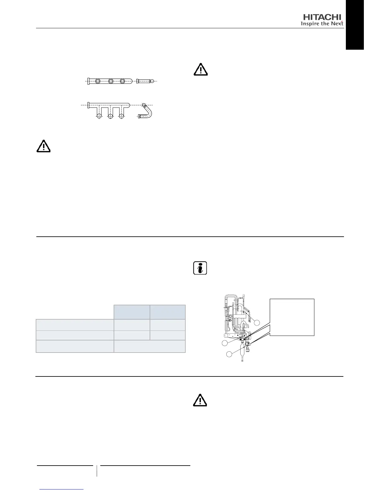
4 Correct position of Triple Branch Pipe (Standard series only).
• Install the header horizontally
Sample: Triple Branch pipe
Gas piping
Liquid piping
13.4.3 Brazing work
C A U T I O N
• Use nitrogen gas for blowing during pipe brazing. If oxygen,
acetylene or uorocarbon gas is used, it will cause an explo-
sion or poisonous gas.
• A lot of oxidation lm will occur inside of tubes if no nitrogen
gas blowing is performed during brazing work. This lm will
be ecked off after operation and will circulate in the cycle,
resulting in clogged expansion valves, etc. This will cause bad
inuence to the compressor.
• Use a reducer valve when nitrogen gas blowing is performed
during brazing. The gas pressure should be maintained within
0.03 to 0.05 Mpa. If a excessively high pressure is applied to
a pipe, it will cause an explosion.
13.4.4 Refrigerant charge
C A U T I O N
• Do not charge OXYGEN, ACETYLENE, or other ammable
and poisonous gases into the refrigerant because an explo-
sion can occur. It is recommended that oxygen free nitrogen
be charged for these types of tests cycle when performing
a leakage test or an airtight test. These types of gases are
extremely dangerous,
• Insulate the unions and are-nuts at the piping connection
part completely.
• Insulate the liquid piping completely to avoid a decrease of
performance; if not, it will cause sweating on the surface of
the pipe.
• Charge refrigerant correctly. Overcharging or insufcient
charging could cause a compressor failure.
• Check for refrigerant leakage in detail. If a large refrigerant
leakage occurred, it would cause difculty with breathing or
harmful gases would occur if a re were being used in the
room.
• If the are nut is tigthened too hard, the are nut may crack
after a long time and cause refrigerant leakage.
13.6 REFRIGERANT CHARGING QUANTITY
When the pressure is measured, use the check joint of gas stop
valve (A), and use the check joint of liquid piping (B) in the gure
below.
At that time, connect the pressure gauge according to the follow-
ing table because of high pressure side and low pressure side
changes by operation mode.
Cooling
Operation
Heating
Operation
Check Joint for Gas Stop Valve “A” Low Pressure High Pressure
Check Joint for Piping “B” High Pressure Low Pressure
Check Joint for Liquid Stop Valve “C”
Exclussive for Vacuum Pump
and Refrigerant Charge
N O T E
Be careful that refrigerant and oil do not splash to the electrical
parts at removing the charge hoses.
C
B
A
The gas stayed at O-ring
screw part is o p e ned
and may mak e sou n d
when removing the cap.
However, it is n ot gas
leakage.
13.5 CAUTION OF THE PRESSURE BY CHECK JOINT
Outdoor Units has been charged with refrigerant for 30m of actual
piping length. An additional refrigerant charged is required in sys-
tems with actual piping length longer than 30m.
1 Determine an additional refrigerant quantity according to the
following procedure, and charge it into the system.
2 Record the additional refrigerant quantity to facilitate service
activities thereafter.
C A U T I O N
• When charging refrigerant accurately measure refrigerant to
be charged.
• Overcharging or undercharging of refrigerant can cause com-
pressor trouble
• In case of actual piping length less than 5 m, consult your
distributor.
 Loading...