Drain piping
25
PMML0317A rev.1 - 11/2013
ENGLISH
14 DRAIN PIPING
15 ELECTRICAL WIRING
1 Ensure that the eld-supplied electrical components (mains
power switches, circuit breakers, wires, connectors and wire
terminals) have been properly selected according to the elec-
trical data indicated. Make sure that they comply with national
and regional electrical codes.
2 Following the Council Directive 2004/108/EC(89/336/EEC),
relating to electromagnetic compatibility, next table indicates:
Maximum permissible system impedance Z
max
at the interface
point of the user’s supply, in accordance with EN61000-3-11
MODEL Z max (Ω) MODEL Z max (Ω)
RAS-3HVNP1E - - -
RAS-4HVNP1E - RAS-4HNP1E -
RAS-4HVRNS3E 0.27 RAS-4HRNS3E -
RAS-5HVNP1E - RAS-5HNP1E -
RAS-6HVNP1E - RAS-6HNP1E -
- - RAS-8HNPE -
- - RAS-8HNCE -
- - RAS-10HNPE -
- - RAS-10HNCE -
3 Harmonics situation of each model regarding IEC 61000-3-2
and IEC 61000-3-12 is as follows:
MODELS SITUATION REGARDING
IEC 61000-3-2 AND IEC 61000-3-12
Ssc “xx”
MODELS
Ssc “xx”
(KVA)
Equipment complying with IEC 61000-3-2
(professional use)
RAS-(4-6)HNP1E
RAS-4H(V)RNS3E
Equipment complying with IEC 61000-3-12 RAS-(3-6)HVNP1E -
Installation restrictions may be applied by au-
thorities regarding the power supply in relation
to harmonics
RAS-(8/10)HNPE
RAS-(8/10)HNCE
4 Check to ensure that the power supply voltage is within +/-
10% of the rated voltage.
5 Check to ensure that power supply has an impedance low
enough to warranty not reduce the starting voltage more than
85% of the rated voltage.
6 Check to ensure that the ground wire is connected.
7 Connect a fuse of specied capacity.
N O T E
Check and test to ensure that if there is more than one source of
power supply, that all are turned OFF.
C A U T I O N
• Check to ensure that screws for terminal block are tightly
tightened.
• Check to ensure that the indoor fan and the outdoor fan have
stopped before electrical wiring work or periodical check is
performed.
• Protect the wires, drain pipe, electrical parts, from rats or other
small animals. If not protected, rats may damage unprotected
parts, and at the worst, a re will occur.
• Wrap the accessory packing around the wires, and plug the
wiring connection hole with the seal material to protect the
product from any condensed water and insects.
• Tightly secure the wires with the cord clamp inside the indoor
unit.
• Lead the wires through the knockout hole in the side cover
when using conduit.
• Secure the cable of the remote control switch with the cord
clamp inside the electrical box.
• Electrical wiring must comply with national and local codes.
Contact your local authority in regards to standards, rules,
regulations, etc.
• Check that the ground wire is securely connected.
• Connect a fuse of specied capacity.
D A N G E R
• Donotconnectofadjustanywiringorconnectionsun-
lessthemainpowerswitchisOFF.
• Checkthattheearthwireissecurelyconnected,tagged
andlockedinaccordancewithnationalandlocalcodes.
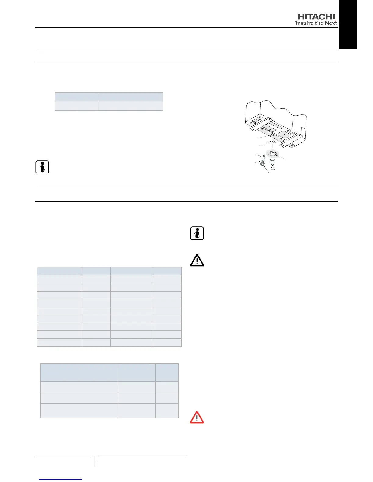
14.1 DRAIN DISCHARGING BOSS
When the base of the outdoor unit is temporarily utilized as a
drain receiver and the drain water in it is discharged, this drain
boss is utilized to connect the drain piping.
Model Applicable Model
DBS-26 All units
Connecting procedure
1 Insert the rubber cap into the drain boss up to the extruded
portions.
2 Insert the boss into the unit base and turn approximately 40
degree counterclockwise.
3 Size of the drain boss is 32 mm (O.D.).
4 A drain pipe should be eld-supplied.
N O T E
Do not use this drain boss set in a cold area, because the drain
water may freeze.
This drain boss is not sufcient to collect all the drain water. If
collecting drain water is completely required, provide a drain-pan
that is bigger than the unit base and install it under the unit with
drainage.
Rubber cap
Drain Boss
Extruded portion
Drain pipe
Drain pipe
Drain hole
of Base
15.1 GENERAL CHECK
 Loading...