26
Electrical wiring
PMML0317A rev.1 - 11/2013
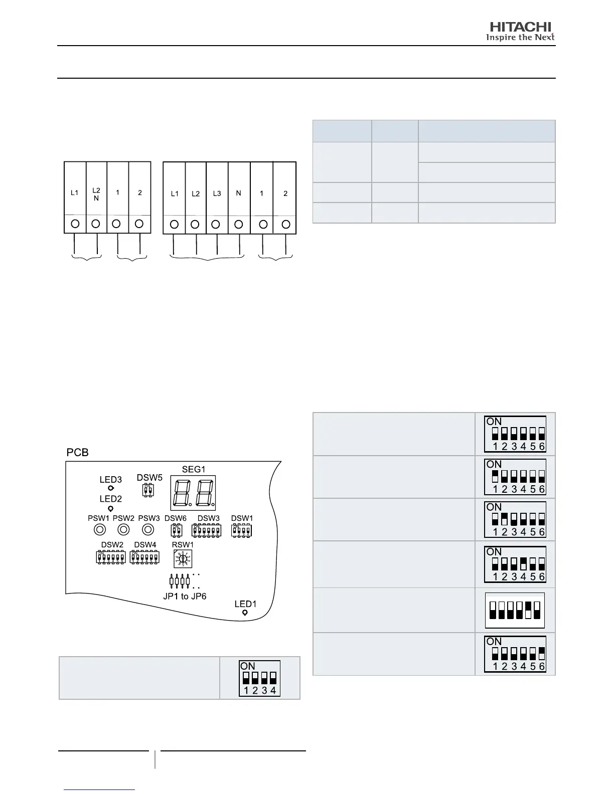
The electrical wiring connection for the outdoor unit is
shown in gure below:
RAS-3HVNP1E
RAS-(4-6)HVNP1E
RAS-4HVRNS3E
RAS-4HRNS3E
RAS-(4-10)HNP(1)E
RAS-(8-10)HNCE
Power supply
1~ 230V
Control cable (5V)
Power supply
3N~ 400V
Control cable (5V)
Table for Terminal Connection between units
Wiring System
Units type
Connection of terminals
Power Supply DC inverter
O.U. to O.U.
L1 to L1, L2 to L2, L3 to L3, N to N
I.U. to I.U.
L1 to L1, N to N)
Operating DC inverter
O.U. to I.U. or I.U. toI.U.
1 to1, 2 to 2
Remote Control DC inverter
I.U. to I.U.
A to A, B to B
O.U.: Outdoor Unit; I.U.: Indoor unit
15.2.1 Setting of DIP Switches for Outdoor Unit
Quantity and Position of DIP Switches.
The location is as follows:
RAS-3HVNP1E, RAS-(4-10)H(V)NP(1)E, RAS-(8-10)HNCE
and RAS-4H(V)RNS3E
DSW1: For Test Run
Factory setting
DSW2: Optional Function Setting
Factory setting
Piping length ≤ 5m
Piping lenght ≥ 30m
Control to support existing pipes or
when using Ø19,05 gas pipe (soft-annealed),
switch ON DSW2 pin 4 in the outdoor unit
PCB
Optional function setting mode (The optional
function selection mode become available)
1 2 3 4 5 6
ON
External input/output setting mode (The input
/ output signals selection mode becomes
avaliable).
15.2 ELECTRICAL WIRING CONNECTION FOR OUTDOOR UNITS
 Loading...