4 Electrical and control settings
Setting of DIP switches and RSW switches
SMGB0099 rev.0 - 12/2016
168
PCB2 settings
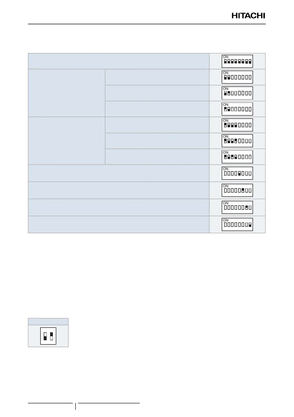
DSW1: Optional functions
Factory setting
1 2
3
4
5 6
7 8
Pins 1 and 2: Capacity control setting
Discharge air control (Control by outlet temperature)
1 2
3
4
5 6
7 8
Indoor air control (Control by inlet temperature)
1 2
3
4
5 6
7 8
External duty control (*1)
1 2
3
4
5 6
7 8
Pins 3 and 4: Duty signal setting (*1)
4~20 mA (Internal 100Ω load impedance)
1 2
3
4
5 6
7 8
0~10 V (Internal 47Ω pull-down resistor)
1 2
3
4
5 6
7 8
0~5 V (Internal 47Ω pull-down resistor)
1 2
3
4
5 6
7 8
Pin 5: Duty mode selection (*2)
1 2
3
4
5 6
7 8
Pin 6: Thermo ON/OFF external input enabled (*3)
1 2
3
4
5 6
7 8
Pin 7: Group controller (Pin 7 ON: group controller; pin 7 OFF: individual controller) (*4)
1 2
3
4
5 6
7 8
Pin 8: Not used
1 2
3
4
5 6
7 8
? NOTE
• (*1): If external duty control is selected (pins 1-2), check the proper selection for the duty signal (pins 3-4).
• (*2): If external duty control is selected (pins 1-2-3-4), then turn pin 5 OFF for absolute reference or ON for incremental reference.
• (*3): The thermo ON/OFF control can be driven externally by an input signal connected to the CN3 socket of the PCB1. The pin 6 of
DSW1 in PCB2 must be switched on, then the input “i1” of CN3 is automatically set for thermo ON/OFF control. The setting of input
“i2” is kept as set on the remote controller.
• (*4) One unit of DX-Interface series 2 is to be set as a group controller, while all the other group members are slave
• Please refer to HITACHI Indoor units Service Manual for further information about the setting and connection of the auxiliary inputs.
DSW2: End resistance
No setting is required.
All units
ON
 Loading...

