2 Unit installation
DX-Interface
SMGB0099 rev.0 - 12/2016
78
Air thermistor
Two air thermistors are supplied inside the control box. The purpose and identication of each one is as follow:
Item
PCB socket /
Thermistor connector colour
PCB socket number Thermistor length (mm)
Inlet air thermistor Blue THM 1 1200
Outlet air thermistor Red THM 2 1200
! CAUTION
In case that the thermistors supplied with the Dx-Interface are not long enough, please make sure that the length extension is properly
done avoiding the sensing distortion and that the joint is properly insulated to avoid any electrical failure.
? NOTE
When tting the air thermistor, remember that they must be secure correctly, in an adequate place to avoid external inuences, like
ambient conditions, and where the air temperature is signicant.
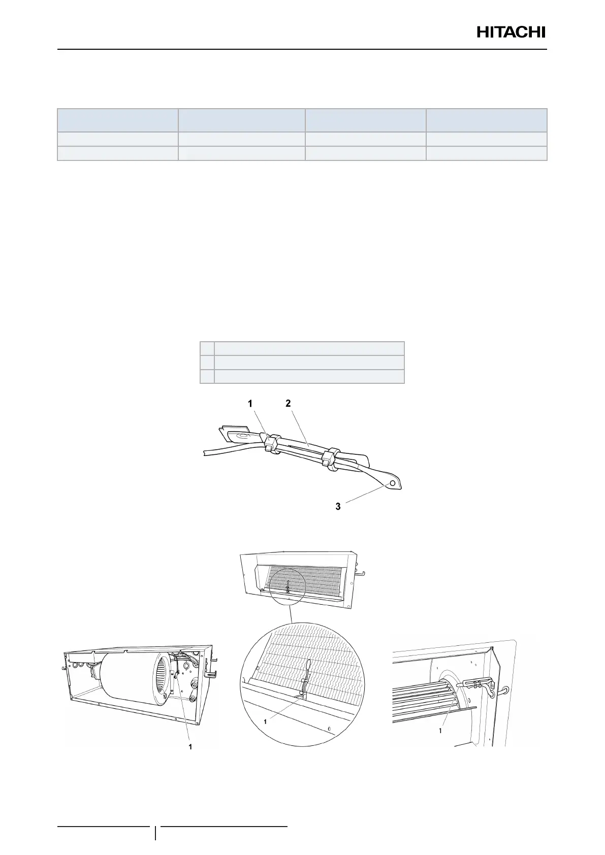
Cable clamp example
! CAUTION
The thermistor must be installed properly in order to avoid water onto the thermistor.
1 Tie (eld supplied)
2 Cable clamp (eld supplied)
3 Thermistor (supplied)
Typical installation
1 Thermistor.
 Loading...

