1. Product range and specifi cations
............................................................................
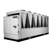
1.1. General data for RCUE40~400AG2
.....................................................................................................
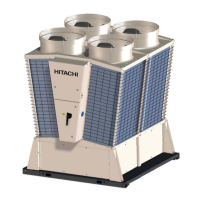
1.2. General data for RHUE40~240AG2
.....................................................................................................
....................................................................................................................
2.1. Check before test run
...........................................................................................................................
2.2. Test run method and check
..................................................................................................................
...............................................................................................................................
2.4. Instruction at delivery
............................................................................................................................
..................................................................................................................................
3 Electrical Wiring Diagram
........................................................................................
3.1. Power Wiring Diagram
..........................................................................................................................
3.2. Power Wiring Diagram (FAN)
...............................................................................................................
.............................................................................................................................
3.4. Input / Output PCB (PCBd)
...................................................................................................................
3.5. Power Wiring Diagram (MCB Option)
...................................................................................................
3.6. Diagram abbreviations descriptions
.....................................................................................................
........................................................................................................
4.1. List of Main Control Function
................................................................................................................
........................................................................................................................................
.............................................................................................................................
4.4. Current limit control
..............................................................................................................................
4.5. Reverse protection control
....................................................................................................................
Restart control after power failure
........................................................................................................
4.7. Operation error/wrong setting prevention control [40 – 40]
.................................................................
4.8. Forced capacity control
........................................................................................................................
4.9. Second water temperature setting
........................................................................................................
4.10. Heat storage operation by external order
.............................................................................................
4.10. Heat storage operation by external order .............................................................................................4.10. Heat storage operation by external order
4.11. Operation by DC24V input (Remote Control)
.......................................................................................
4.12. Installation of switch for snow measure (Fan manual operation)
.........................................................
4.13. Switch for confi rmation of high pressure cut
.........................................................................................
4.14 Antifreeze control in winter
...................................................................................................................
4.14 Antifreeze control in winter ...................................................................................................................4.14 Antifreeze control in winter
4.15. Saving energy priority mode, silence priority mode (night shift), only cooling
......................................
4.16. Defrost (only air-cooled heat pump type)
.............................................................................................
4.17. Thermo off selection function
...............................................................................................................
 Loading...