11.4.12.1 Verifying the settings
GUID-708C4033-3111-481F-9868-FF207C18C9F9 v2
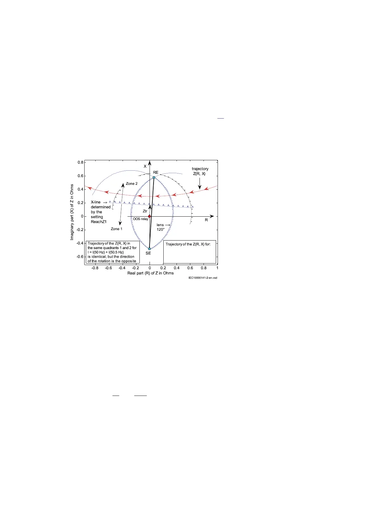
The test of the out-of-step protection function is made to verify that the trip is issued if the following
events happen.
• the impedance, seen by the function, enters the lens characteristic from one side and leaves it
from the opposite side
• the trip is issued according to the settings TripAngle and tBreaker
The tripping zone needs to be detected and confirmed. The test may be performed by taking into
account the following key points that are shown in Figure
43:
• the point RE (RE = Receiving End)
• the intersection between the line segment SE-RE and the X-line, which is defined through the
setting ReachZ1
• the point SE (SE = Sending End)
I = I(50 Hz) + I(49.5 Hz)
IEC10000141 V2 EN-US
Figure 43: Trajectory of the impedance Z(R, X) for the injected current with two components:
a 50 Hz component and a 49.5 Hz current component
The test of the out-of-step protection function requires the injection of the analog quantities for a quite
long time. The rating of the analogue channels must be considered in order to avoid any hardware
damage. The test current is lower than the continuous permissive overload current I
ovrl
of the
protection current channels of the transformer module.
If the rated secondary current I
rs
of the analog channel is 1 A, then the maximum current test I
ts
is
I I I A
ts ovrl rs
≤ = × =4 4
EQUATION14041 V1 EN-US (Equation 5)
If the CT of the generator has ratio 9000/1 A, then in primary values
I I I
I
I
A
t ovrl p ovrl
rp
rs
≤ = × = × =
,
4
9000
1
36000
EQUATION14042 V1 EN-US (Equation 6)
Reference is made to the numerical values of the example, explained in the “Setting guidelines” of
the Application Manual. A test current equal to 2.5 time the base current of the generator is chosen;
this choice is related to the selected test voltage that is applied while testing the point SE and RE.
I I A
t Base
= × = × =2 5 2 5 8367 20918. .
EQUATION14043 V1 EN-US
(Equation 7)
Section 11 1MRK 504 165-UEN Rev. K
Testing functionality by secondary injection
138 Transformer protection RET670
Commissioning manual
© 2017 - 2022 Hitachi Energy. All rights reserved
 Loading...